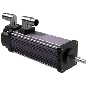
GSM Series
STANDARD CAPACITY ELECTRIC LINEAR ACTUATORS FOR EXCEPTIONAL RESULTS
Industrial - Exlar
The GSM Series is a Legacy Product. Need a comparable replacement, try our GTX Series actuators!
Industrial - Exlar
The GSM Series is a Legacy Product. Need a comparable replacement, try our GTX Series actuators!
| Models: |
GSM20, GSM30, GSM40 |
| Frame Sizes: |
2, 3, 4 in (60, 80, 100 mm) |
| Stroke Length: |
3, 4, 6, 8, 10, 12, 14, 18 in |
| Screw Lead: |
0.1, 0.2, 0.4, 0.5, 0.75 in (2, 5, 10, 13, 19 mm) |
| Linear Speeds: |
up to 37.5 in/s (952 mm/s) |
| Continuous Thrust Capacity: |
103 to 3,457 lbf (458 to 15.3 kN) |
| Standards/Ratings: |
UL Class 180H insulation, IP54S (IP65S op |
|
Back to Top
|
Motor Stacks |
|
1 |
1 |
1 |
2 |
2 |
2 |
|---|---|---|---|---|---|---|---|
|
Screw Lead Designator |
|
1 |
2 |
4 |
1 |
2 |
4 |
|
Screw Lead |
in |
0.1 |
0.2 |
0.4 |
0.1 |
0.2 |
0.4 |
|
mm |
2.54 |
5.08 |
10.16 |
2.54 |
5.08 |
10.16 |
|
|
Continuous Force (Motor Limited) |
lbf |
367 |
195 |
103 |
578 |
307 |
163 |
|
N |
1632 |
867 |
459 |
2571 |
1366 |
723 |
|
|
Max Velocity |
in/sec |
8.3 |
16.8 |
33.3 |
8.3 |
16.8 |
33.3 |
|
mm/sec |
211.7 |
423.3 |
846.7 |
211.7 |
423.3 |
846.7 |
|
|
Friction Torque (standard screw) |
in-lbf |
1 |
1 |
1 |
1.1 |
1.1 |
1.1 |
|
N-m |
0.12 |
0.12 |
0.12 |
0.12 |
0.12 |
0.12 |
|
|
Friction Torque (preloaded screw) |
in-lbf |
1.25 |
1.25 |
1.25 |
1.25 |
1.25 |
1.25 |
|
N-m |
0.14 |
0.14 |
0.14 |
0.14 |
0.14 |
0.14 |
|
|
Min Stroke |
in |
3 |
3 |
3 |
3 |
3 |
3 |
|
mm |
76 |
76 |
76 |
76 |
76 |
76 |
|
|
Max Stroke |
in |
12 |
12 |
12 |
12 |
12 |
12 |
|
mm |
305 |
305 |
305 |
305 |
305 |
305 |
|
|
C_a (Dynamic Load Rating) |
lbf |
1568 |
1219 |
738 |
1568 |
1219 |
738 |
|
N |
6970 |
5422 |
3283 |
6970 |
5422 |
3283 |
|
|
Inertia (zero stroke) |
lb-in-s^2 |
0.0007758 |
0.0007758 |
0.0007758 |
0.00086 |
0.00086 |
0.00086 |
|
Kg-m^2 |
0.0000008766 |
0.0000008766 |
0.0000008766 |
0.0000009717 |
0.0000009717 |
0.0000009717 |
|
|
Inertia Adder (per inch of stroke) |
lb-in-s^2/in |
0.00004667 |
0.00004667 |
0.00004667 |
0.00004667 |
0.00004667 |
0.00004667 |
|
Kg-m^2/in |
0.00000005273 |
0.00000005273 |
0.00000005273 |
0.00000005273 |
0.00000005273 |
0.00000005273 |
|
|
Weight (zero stroke) |
lb |
4.5 |
4.5 |
4.5 |
5 |
5 |
5 |
|
Kg |
2.04 |
2.04 |
2.04 |
2.27 |
2.27 |
2.27 |
|
|
Weight Adder (per inch of stroke) |
lb |
0.5 |
0.5 |
0.5 |
0.5 |
0.5 |
0.5 |
|
Kg |
0.23 |
0.23 |
0.23 |
0.23 |
0.23 |
0.23 |
Printable view
|
Motor Stacks |
1 |
1 |
1 |
2 |
2 |
2 |
|
|---|---|---|---|---|---|---|---|
|
Screw Lead Designator |
1 |
2 |
5 |
1 |
2 |
5 |
|
|
Screw Lead |
in |
0.1 |
0.2 |
0.5 |
0.1 |
0.2 |
0.5 |
|
mm |
2.54 |
5.08 |
12.7 |
2.54 |
5.08 |
12.7 |
|
|
Continuous Force (Motor Limited) |
lbf |
792 |
449 |
190 |
1277 |
724 |
306 |
|
N |
3521 |
1995 |
845 |
5680 |
3219 |
1363 |
|
|
Max Velocity |
in/sec |
5 |
10 |
25 |
5 |
10 |
25 |
|
mm/sec |
127 |
254 |
635 |
127 |
254 |
635 |
|
|
Friction Torque (standard screw) |
in-lbf |
1.5 |
1.5 |
1.5 |
1.7 |
1.7 |
1.7 |
|
N-m |
0.17 |
0.17 |
0.17 |
0.19 |
0.19 |
0.19 |
|
|
Friction Torque (preloaded screw) |
in-lbf |
1.75 |
1.75 |
1.75 |
1.75 |
1.75 |
1.75 |
|
N-m |
0.2 |
0.2 |
0.2 |
0.2 |
0.2 |
0.2 |
|
|
Min Stroke |
in |
3 |
3 |
3 |
3 |
3 |
3 |
|
mm |
76 |
76 |
76 |
76 |
76 |
76 |
|
|
Max Stroke |
in |
18 |
18 |
18 |
18 |
18 |
18 |
|
mm |
457 |
457 |
457 |
457 |
457 |
457 |
|
|
C_a (Dynamic Load Rating) |
lbf |
3310 |
3570 |
3016 |
3310 |
3570 |
3016 |
|
N |
14724 |
15880 |
13416 |
14724 |
15880 |
13416 |
|
|
Inertia (zero stroke) |
lb-in-s^2 |
0.002655 |
0.002655 |
0.002655 |
0.002829 |
0.002829 |
0.002829 |
|
Kg-m^2 |
0.000003000 |
0.000003196 |
|||||
|
Inertia Adder (per inch of stroke) |
lb-in-s^2/in |
0.0001424 |
|||||
|
Kg-m^2/in |
0.0000001609 |
||||||
|
Weight (zero stroke) |
lb |
6.5 |
6.5 |
6.5 |
7.65 |
7.65 |
7.65 |
|
Kg |
2.95 |
2.95 |
2.95 |
3.47 |
3.47 |
3.47 |
|
|
Weight Adder (per inch of stroke) |
lb |
1.1 |
1.1 |
1.1 |
1.1 |
1.1 |
1.1 |
|
Kg |
0.5 |
0.5 |
0.5 |
0.5 |
0.5 |
0.5 |
|
|
Motor Stator |
|
118 |
138 |
158 |
168 |
218 |
238 |
258 |
268 |
|---|---|---|---|---|---|---|---|---|---|
|
Bus Voltage |
Vrms |
115 |
230 |
400 |
460 |
115 |
230 |
400 |
460 |
|
Speed @ Bus Voltage |
rpm |
3000 |
3000 |
3000 |
3000 |
3000 |
3000 |
3000 |
3000 |
|
RMS Sinusoidal Commutation |
|||||||||
|
Continuous Motor Torque |
lbf-in |
16.9 |
16.8 |
16.3 |
16 |
26.9 |
27.1 |
26.7 |
27 |
|
Nm |
1.91 |
1.9 |
1.84 |
1.81 |
3.04 |
3.06 |
3.01 |
3.05 |
|
|
Torque Constant (Kt) (+/- 10% @ 25°C) |
lbf-in/A |
4.4 |
8.7 |
15.5 |
17.5 |
4.4 |
8.7 |
15.5 |
17.5 |
|
|
Nm/A |
0.49 |
0.99 |
1.75 |
1.97 |
0.49 |
0.99 |
1.75 |
1.97 |
|
Continuous Current Rating |
A |
4.3 |
2.2 |
1.2 |
1 |
6.9 |
3.5 |
1.9 |
1.7 |
|
Peak Current Rating |
A |
8.6 |
4.3 |
2.4 |
2 |
13.8 |
6.9 |
3.8 |
3.4 |
|
O-PK Sinusoidal Commutation |
|||||||||
|
Continuous Motor Torque |
lbf-in |
16.9 |
16.8 |
16.3 |
16 |
26.9 |
27.1 |
26.7 |
27 |
|
Nm |
1.91 |
1.9 |
1.84 |
1.81 |
3.04 |
3.06 |
3.01 |
3.05 |
|
|
Torque Constant (Kt) (+/- 10% @ 25°C) |
lbf-in/A |
3.1 |
6.2 |
11 |
12.4 |
3.1 |
6.2 |
11 |
12.4 |
|
Nm/A |
0.35 |
0.7 |
1.24 |
1.4 |
0.35 |
0.7 |
1.24 |
1.4 |
|
|
Continuous Current Rating |
A |
6.1 |
3 |
1.7 |
1.4 |
9.7 |
4.9 |
2.7 |
2.4 |
|
Peak Current Rating |
A |
12.2 |
6.1 |
3.3 |
2.9 |
19.5 |
9.8 |
5.4 |
4.9 |
|
Motor Stator Data |
|||||||||
|
Voltage Constant (Ke) (+/- 10% @ 25°C) |
Vrms/Krpm |
29.8 |
59.7 |
105.8 |
119.3 |
29.8 |
59.7 |
105.8 |
119.3 |
|
Vpk/Krpm |
42.2 |
84.4 |
149.7 |
168.7 |
42.2 |
84.4 |
149.7 |
168.7 |
|
|
Pole Configuration |
8 |
8 |
8 |
8 |
8 |
8 |
8 |
8 |
|
|
Resistance (L-L)(+/- 5% @ 25°C) |
Ohms |
2.7 |
10.8 |
36.3 |
47.9 |
1.1 |
4.4 |
14.1 |
17.6 |
|
Inductance (L-L)(+/- 15%) |
mH |
7.7 |
30.7 |
96.8 |
123 |
3.7 |
14.7 |
46.2 |
58.7 |
|
Brake Inertia |
lbf-in-sec^2 |
0.00033 |
0.00033 |
0.00033 |
0.00033 |
0.00033 |
0.00033 |
0.00033 |
0.00033 |
|
Kg-cm^2 |
0.38 |
0.38 |
0.38 |
0.38 |
0.38 |
0.38 |
0.38 |
0.38 |
|
|
Brake Current @ 24 VDC |
A |
0.5 |
0.5 |
0.5 |
0.5 |
0.5 |
0.5 |
0.5 |
0.5 |
|
Brake Holding Torque |
lbf-in |
40 |
40 |
40 |
40 |
40 |
40 |
40 |
40 |
|
Nm |
4.5 |
4.5 |
4.5 |
4.5 |
4.5 |
4.5 |
4.5 |
4.5 |
|
|
Brake Engage/Disengage Time |
ms |
19/29 |
19/29 |
19/29 |
19/29 |
19/29 |
19/29 |
19/29 |
19/29 |
|
Mechanical Time Constant (tm), ms |
min |
4.9 |
4.9 |
5.2 |
5.4 |
2 |
2 |
2 |
2 |
|
max |
9.4 |
9.5 |
10.1 |
10.5 |
3.9 |
3.8 |
3.9 |
3.8 |
|
|
Electrical Time Constant (te) |
ms |
2.9 |
2.8 |
2.7 |
2.6 |
3.3 |
3.4 |
3.3 |
3.3 |
|
Insulation Class |
180 (H) |
180 (H) |
180 (H) |
180 (H) |
180 (H) |
180 (H) |
180 (H) |
180 (H) |
|
Printable view
|
Motor Stacks |
|
1 |
1 |
1 |
1 |
2 |
2 |
2 |
2 |
|---|---|---|---|---|---|---|---|---|---|
|
Screw Lead Designator |
1 |
2 |
5 |
8 |
1 |
2 |
5 |
8 |
|
|
Screw Lead |
in |
0.1 |
0.2 |
0.5 |
0.75 |
0.1 |
0.2 |
0.5 |
0.75 |
|
mm |
2.54 |
5.08 |
12.7 |
19.05 |
2.54 |
5.08 |
12.7 |
19.05 |
|
|
Continuous Force (Motor Limited) |
lbf |
2089 |
1194 |
537 |
358 |
3457 |
1975 |
889 |
593 |
|
N |
9293 |
5310 |
2390 |
1593 |
15377 |
8787 |
3954 |
2636 |
|
|
Max Velocity |
in/sec |
5 |
10 |
25 |
37.5 |
5 |
10 |
25 |
37.5 |
|
mm/sec |
127 |
254 |
635 |
953 |
127 |
254 |
635 |
953 |
|
|
Friction Torque (standard screw) |
in-lbf |
2.7 |
2.7 |
2.7 |
2.7 |
3 |
3 |
3 |
3 |
|
N-m |
0.31 |
0.31 |
0.31 |
0.31 |
0.34 |
0.34 |
0.34 |
0.34 |
|
|
Friction Torque (preloaded screw) |
in-lbf |
3 |
3 |
3 |
3 |
3 |
3 |
3 |
3 |
|
N-m |
0.34 |
0.34 |
0.34 |
0.34 |
0.34 |
0.34 |
0.34 |
0.34 |
|
|
Min Stroke |
in |
4 |
4 |
4 |
4 |
6 |
6 |
6 |
6 |
|
mm |
102 |
102 |
102 |
102 |
152 |
152 |
152 |
152 |
|
|
Max Stroke |
in |
18 |
18 |
18 |
12 |
18 |
18 |
18 |
12 |
|
mm |
457 |
457 |
457 |
305 |
457 |
457 |
457 |
305 |
|
|
C_a (Dynamic Load Rating) |
lbf |
4736 |
4890 |
4218 |
3328 |
4736 |
4890 |
4218 |
3328 |
|
N |
21067 |
21751 |
18763 |
14804 |
21067 |
21751 |
18763 |
14804 |
|
|
Inertia (zero stroke) |
lb-in-s^2 |
0.01132 |
0.01132 |
0.01132 |
0.01132 |
0.01232 |
0.01232 |
0.01232 |
0.01232 |
|
Kg-m^2 |
0.001279 |
0.001279 |
0.001279 |
0.001279 |
0.001392 |
0.001392 |
0.001392 |
0.001392 |
|
|
Inertia Adder (per inch of stroke) |
lb-in-s^2/in |
0.000564 |
0.000564 |
0.000564 |
0.000564 |
0.000564 |
0.000564 |
0.000564 |
0.000564 |
|
Kg-m^2/in |
0.0000006372 |
||||||||
|
Weight (zero stroke) |
lb |
8 |
8 |
8 |
8 |
11.3 |
11.3 |
11.3 |
11.3 |
|
Kg |
3.63 |
3.63 |
3.63 |
3.63 |
5.13 |
5.13 |
5.13 |
5.13 |
|
|
Weight Adder (per inch of stroke) |
lb |
2 |
2 |
2 |
2 |
2 |
2 |
2 |
2 |
|
Kg |
0.91 |
0.91 |
0.91 |
0.91 |
0.91 |
0.91 |
0.91 |
0.91 |
|
|
Motor Stator |
|
118 |
138 |
158 |
168 |
218 |
238 |
258 |
268 |
|---|---|---|---|---|---|---|---|---|---|
|
Bus Voltage |
Vrms |
115 |
230 |
400 |
460 |
115 |
230 |
400 |
460 |
|
Speed @ Bus Voltage |
rpm |
3000 |
3000 |
3000 |
3000 |
3000 |
3000 |
3000 |
3000 |
|
RMS Sinusoidal Commutation |
|||||||||
|
Continuous Motor Torque |
lbf-in |
47.5 |
47.5 |
45.9 |
45.4 |
75.1 |
78.6 |
78.7 |
79.5 |
|
Nm |
5.37 |
5.36 |
5.19 |
5.13 |
8.49 |
8.89 |
8.89 |
8.99 |
|
|
Torque Constant (Kt) (+/- 10% @ 25°C) |
lbf-in/A |
4.1 |
8.2 |
14.5 |
16.8 |
4.1 |
8.2 |
14.5 |
16.8 |
|
Nm/A |
0.46 |
0.93 |
1.64 |
1.9 |
0.46 |
0.93 |
1.64 |
1.9 |
|
|
Continuous Current Rating |
A |
12.9 |
6.5 |
3.5 |
3 |
20.5 |
10.7 |
6 |
5.3 |
|
Peak Current Rating |
A |
25.9 |
12.9 |
7.1 |
6 |
40.9 |
21.4 |
12.1 |
10.6 |
|
O-PK Sinusoidal Commutation |
|||||||||
|
Continuous Motor Torque |
lbf-in |
47.5 |
47.5 |
45.9 |
45.4 |
75.1 |
78.6 |
78.7 |
79.5 |
|
Nm |
5.37 |
5.36 |
5.19 |
5.13 |
8.49 |
8.89 |
8.89 |
8.99 |
|
|
Torque Constant (Kt) (+/- 10% @ 25°C) |
lbf-in/A |
2.9 |
5.8 |
10.3 |
11.9 |
2.9 |
5.8 |
10.3 |
11.9 |
|
Nm/A |
0.33 |
0.66 |
1.16 |
1.34 |
0.33 |
0.66 |
1.16 |
1.34 |
|
|
Continuous Current Rating |
A |
18.3 |
9.1 |
5 |
4.3 |
28.9 |
15.1 |
8.5 |
7.5 |
|
Peak Current Rating |
A |
36.6 |
18.3 |
10 |
8.6 |
57.9 |
30.3 |
17.1 |
15 |
|
Motor Stator Data |
|||||||||
|
Voltage Constant (Ke) (+/- 10% @ 25°C) |
Vrms/Krpm |
28 |
56 |
99.3 |
114.6 |
28 |
56 |
99.3 |
114.6 |
|
Vpk/Krpm |
39.6 |
79.2 |
140.5 |
162.1 |
39.6 |
79.2 |
140.5 |
162.1 |
|
|
Pole Configuration |
8 |
8 |
8 |
8 |
8 |
8 |
8 |
8 |
|
|
Resistance (L-L)(+/- 5% @ 25°C) |
Ohms |
0.42 |
1.7 |
5.7 |
7.8 |
0.2 |
0.72 |
2.26 |
3 |
|
Inductance (L-L)(+/- 15%) |
mH |
3 |
11.9 |
37.5 |
49.9 |
1.2 |
5.4 |
18.2 |
23.1 |
|
Brake Inertia |
lb-in-sec^2 |
0.00096 |
0.00096 |
0.00096 |
0.00096 |
0.00096 |
0.00096 |
0.00096 |
0.00096 |
|
Kg-cm^2 |
1.08 |
1.08 |
1.08 |
1.08 |
1.08 |
1.08 |
1.08 |
1.08 |
|
|
Brake Current @ 24 VDC |
A |
0.67 |
0.67 |
0.67 |
0.67 |
0.67 |
0.67 |
0.67 |
0.67 |
|
Brake Holding Torque |
bf-in |
97 |
97 |
97 |
97 |
97 |
97 |
97 |
97 |
|
Nm |
11 |
11 |
11 |
11 |
11 |
11 |
11 |
11 |
|
|
Brake Engage/Disengage Time |
ms |
20/29 |
20/29 |
20/29 |
20/29 |
20/29 |
20/29 |
20/29 |
20/29 |
|
Mechanical Time Constant (tm), ms |
min |
4.5 |
4.5 |
4.8 |
4.9 |
2.1 |
1.9 |
1.9 |
1.9 |
|
max |
6 |
6 |
6.4 |
6.6 |
2.8 |
2.6 |
2.6 |
2.5 |
|
|
Electrical Time Constant (te) |
ms |
7 |
7 |
6.6 |
6.4 |
5.9 |
7.5 |
8 |
7.8 |
|
Insulation Class |
180 (H) |
180 (H) |
180 (H) |
180 (H) |
180 (H) |
180 (H) |
180 (H) |
180 (H) |
|
Printable view
Please log in or register to use our quote request tool, with this you can view and download 3D and 2D models and drawings, as well as build and submit a quote request.
If you do not have a login, please proceed to the registration page
If you currently have an Exlar website account and would like to delete it, please contact

