GTF Series
Integrated Motor | Actuator
Industrial - Exlar
For Food & Beverage / Packaging Applications
Innovation
Benefits
Features
Industrial - Exlar
For Food & Beverage / Packaging Applications
Innovation
Benefits
Features
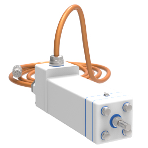
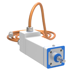
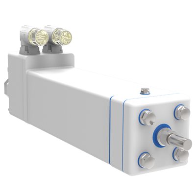
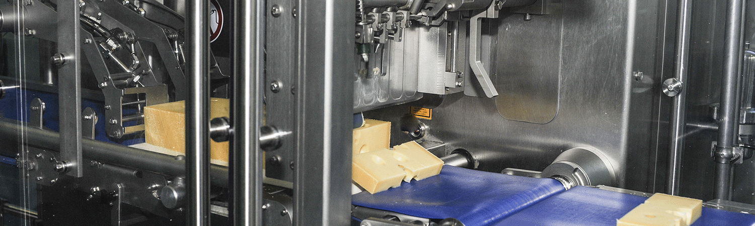
Our newest application-specific actuators make it easier for machine builders to design machines that meet food processing certifications including USDA, 3-A, BISSC, EHEDG, and NSF. The hygienic GTF integrated motor actuator is completely sealed and smooth reducing harborage and keeping out contaminants even during light washdown cleaning.
The GTF is perfect for food and beverage processing applications like dispensing, slicing, dicing, sealing, and pressing.
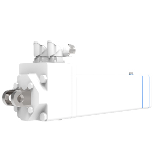
With a variety of frame sizes and mounting options, we are sure you will find exactly what you need. Give one of our representatives a call today!
| Model | Frame Size mm (in) | Nominal Stroke mm ( in) | Peak Force N (lbf) | Continuous Force N (lbf) | Max Speed mm/s (in/s) |
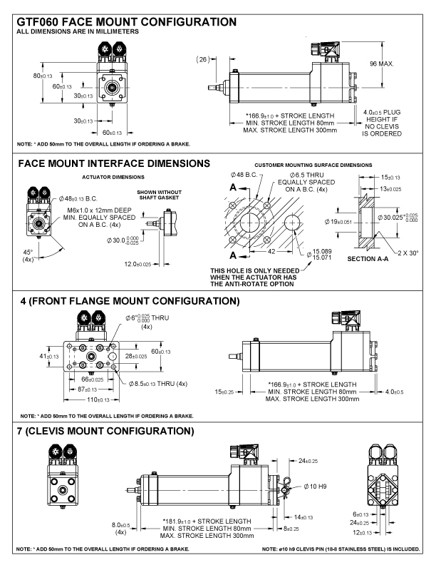
| GTF060 | 60 (2.36) | 80 - 300 (3 - 12) | AC - 5,336 (1,200) | AC - 2,668 (600) | AC - 1,270 (50.0) |
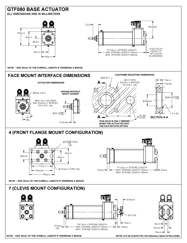
| GTF080 | 80 (3.15) | 100 - 450 (4 - 18) | AC - 16,730 (3,762) | AC - 8,365 (1,881) | AC - 1,270 (50.0) |
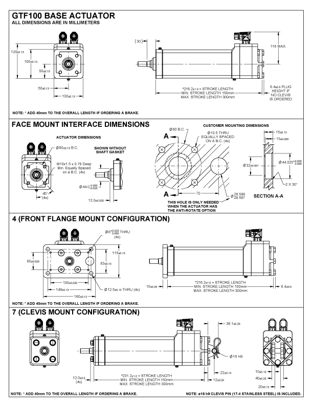
| GTF100 | 100 (3.94) | 150 - 300 (6 - 12) | AC - 30,784 (6,920) | AC - 15,392 (3,460) | AC - 953 (37.5) |
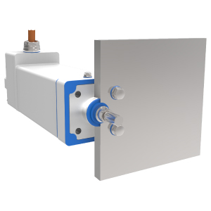
GTF Integrated Motor Actuator for Food & Beverage
The GTF extends Exlar’s popular high-force GTX linear actuators into applications that require hygienic machines in food & beverage, packaging, and pharmaceutical automation systems.
The GTF offers flexible solutions coupled with low maintenance features and proven reliability. The GTF food grade actuator mirrors the performance of Curtiss-Wright’s standard Exlar GTX actuators and incorporates features to make it easier for machines to achieve hygienic certifications like USDA, 3-A, BISSC, EHEDG, and NSF.
Related Industries
|
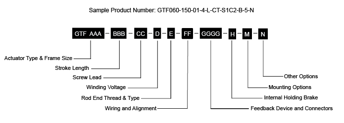
AAA = GTF Integrated Motor / Actuator BBB = Stroke Length
CC = Screw Lead D = Winding Voltage E = Rod End Thread & Type |
FF = Wiring and Alignment GGGG = Feedback Device and Connectors H= Internal Holding Brake M = Mounting Options N = Other Options
|
|
Drive Manufacturer |
Wiring & |
Resolver |
Incremental |
SICK Hiperface Absolute Encoder |
SICK Hiperface DSL Absolute Encoder |
Heidenhain EnDat 2.1 Absolute Encoder 1 |
Heidenhain Endat 2.2 Absolute Encoder 2 |
|---|---|---|---|---|---|---|---|
|
AMK |
AK |
R1A1 |
|
|
|
H1A1 |
|
|
B&R Automation |
BR |
R1A1 |
|
|
|
H1A2 |
H3A83 |
|
Baldor |
BD |
R1A1 |
|
|
|
H1A1 |
|
|
Baumueller |
BM |
R1A1 |
|
S1A1 |
|
H1A2 |
|
|
Beckhoff Automation |
BE |
|
|
|
S4C03 |
H1A2 |
H3C23 |
|
Control Techniques/Nidec |
CT |
R2B1 |
E1B2 |
S1B1 |
|
H1B2 |
|
|
Elau/Schneider |
EU |
|
|
S1A14 |
|
|
|
|
Elmo Motion Control |
EL |
R1B1 |
E1B2 |
|
|
H1B2 |
|
|
Curtiss-Wright Exlar |
EX |
R1A1 |
E1A2 |
S1A2 |
|
H1A2 |
|
|
Curtiss-Wright Exlar Flying Lead Cables |
EX | R1Zx5 | E1Zx5 | S1Zx5 | H1Zx5 | ||
|
Infranor |
IF |
R1B2 |
|
S1B2 |
|
|
|
|
Bosch-Rexroth |
IN |
|
|
S2D34 |
|
H1D3 |
|
|
Kollmorgan |
KM |
R1A1 |
E1A2 |
|
|
H1A2 |
|
|
LTI |
LS |
R2A1 |
|
S1A2 |
|
|
|
|
Lenze |
LZ |
R1B1 |
|
S1B1 |
|
|
|
|
Parker |
PC |
R1B1 |
E1B2 |
|
|
H1B2 |
|
|
Rockwell Automation |
RA |
|
E1C2 |
S1C24 |
S3CO4 |
|
|
|
Rockwell Automation Extension Cable with Connector |
RA |
S3Kx4, 5 |
|||||
|
Siemens |
SM |
R1B1 |
|
|
|
H1B2 |
|
|
Stober Drives |
SB |
R4A1 |
|
|
|
H1A1 |
1Synchronous serial EnDat 2.1 with 1 Vpp Incremental Signals (EnDat01)
2Synchronous serial EnDat 2.2 without Incremental Signals (EnDat22)
3Supports Functional Safety
4Encoder is pre-programmed for operation with the manufacturer's servo drives.
5x=Refer to length options in feedback and connector tables
** Some options are not available with every configuration. For options or specials not listed above contact your local representative.
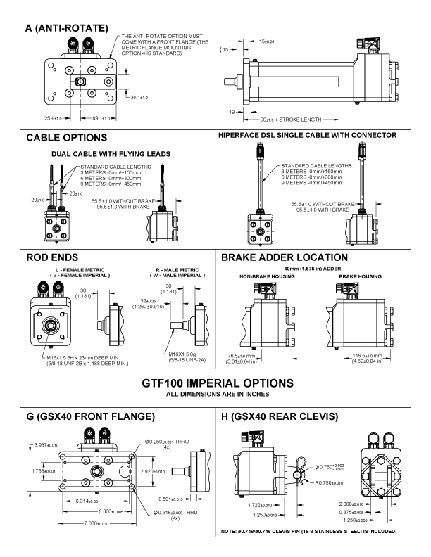
Rear Clevis, Metric
Rear clevis mount, allows actuator to pivot while in motion
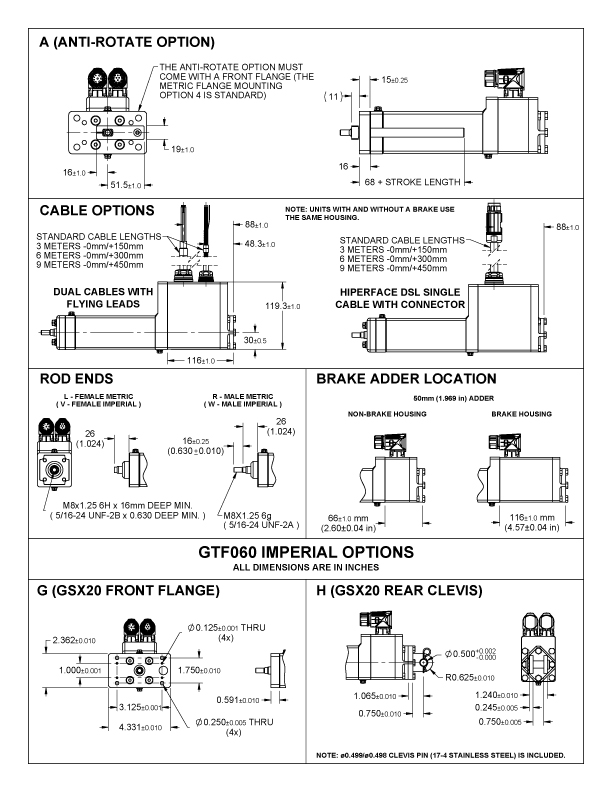
Stainless Steel Rod Option
All thread options on the GTF product line are available in 17-4 stainless steel. This option provides improved corrosion resistance for the main rod of the actuator. This option can be beneficial in applications where the rod could be exposed to harsh chemicals or outdoor environments.
|
Back to Top
| STROKE LENGTH MM (IN) | SCREW LEAD MM (IN) | CONTINUOUS FORCE RATING N (LBF) | MAX VELOCITY MM/S (IN/S) | DYNAMIC LOAD RATING N (LBF) | ARMATURE INERTIA KG-M^2 (IN-LB-S^2) | |
|---|---|---|---|---|---|---|
| Maximum velocities listed at maximum voltages. Do not exceed 2X the continuous force rating during operation. Configured stroke lengths available. Consult Exlar sales representative. Dynamic load ratings valid at forces up to 2X the continuous force rating. Continuous force rating based upon 25° C ambient conditions |
||||||
|
GTF060-80-01 |
80 (3.2) |
2.54 (0.1) |
2,668 (600) |
318 (12.5) |
9,230 (2,075) |
0.00007367 (0.000652) |
|
GTF060-80-02 |
5.08 (0.2) |
1,900 (427) |
635 (25.0) |
6,850 (1,540) |
||
|
GTF060-80-04 |
10.2 (0.4) |
1,006 (226) |
1,270 (50.0) |
5,471 (1,230) |
||
|
GTF060-150-01 |
150 (5.9) |
2.54 (0.1) |
2,668 (600) |
318 (12.5) |
9,230 (2,075) |
0.00008689 (0.000769) |
|
GTF060-150-02 |
5.08 (0.2) |
1,900 (427) |
635 (25.0) |
6,850 (1,540) |
||
|
GTF060-150-04 |
10.2 (0.4) |
1,006 (226) |
1,270 (50.0) |
5,471 (1,230) |
||
|
GTF060-300-01 |
300 (11.8) |
2.54 (0.1) |
2,668 (600) |
318 (12.5) |
9,230 (2,075) |
0.00011537 (0.001021) |
|
GTF060-300-02 |
5.08 (0.2) |
1,900 (427) |
635 (25.0) |
6,850 (1,540) |
||
|
GTF060-300-04 |
10.2 (0.4) |
1,006 (226) |
1,270 (50.0) |
5,471 (1,230) |
||
| MOTOR VOLTAGE | 4 (AC) | |||
|---|---|---|---|---|
| Max Bus Voltage | VAC | 230/460 Vrms | ||
| Speed @ Bus Voltage | RPM | 5000/7500 | ||
| Actuator Lead | in | 0.1 | 0.2 | 0.4 |
| RMS Sinusoidal Commutation | ||||
| Continuous Motor Torque | Nm | 1.35 | 1.81 | 1.81 |
| lbf-in | 11.9 | 16.0 | 16.0 | |
| Continuous Current Rating | A | 3.0 | 4.0 | 4.0 |
| Peak Current Rating | A | 6.0 | 8.0 | 8.0 |
| Torque Constant (Kt) (+/– 10% @ 25˚C) | Nm/A | 0.5 | ||
| lbf-in/A | 4.5 | |||
| Voltage Constant (Ke) (+/– 10% @ 25˚C) | V/kRPM | 30.5 | ||
| 0 - Peak Sinusoidal Commutation | ||||
| Continuous Motor Torque | Nm | 1.8 | ||
| lbf-in | 16 | |||
| Continuous Current Rating | A | 5.7 | ||
| Peak Current Rating | A | 11.3 | ||
| Torque Constant (Kt) (+/– 10% @ 25˚C) | Nm/A | 0.35 | ||
| lbf-in/A | 3.2 | |||
| Voltage Constant (Ke) (+/– 10% @ 25˚C) | V/kRPM | 43.1 | ||
| Pole Configuration | Number of Poles | 8 | ||
| Resistance (L-L) (+/– 5% @ 25˚C) | Ohms | 2.8 | ||
| Inductance (L-L)(+/– 15%) | mH | 13.8 | ||
| Electrical Time Constant | ms | 4.9 | ||
| Insulation Class | 460 VAC Max, 180°C (Class H) | |||
Specifications subject to change without notice
Test data derived using NEMA recommended aluminum heatsink 10" x 10" x 1/4" at 25 °C ambient
Vac Class winding operational compatible with drive voltages up to 460 Vac
Rotational speed approximately proportional to drive input voltage
| Description | kg (lb) |
|---|---|
|
GTF060-80 |
3.2 (7.0) |
|
GTF060-150 |
3.7 (8.1) |
|
GTF060-300 |
4.8 (10.5) |
|
Brake Adder |
0.7 (1.4) |
|
Stainless-steel Rear Clevis (7) |
0.2 (0.5) |
|
Stainless-steel Standard Clevis (D) |
0.3 (0.7) |
| Stainless-steel Front Flange - Metric (4) |
0.63 (1.38) |
| Stainless-steel Front Flange - Standard (G) |
0.65 (1.43) |
| Stainless-steel Anti-Rotate Assembly (A) - 80 |
0.23 (0.52) |
| Stainless-steel Anti-Rotate Assembly (A) - 150 |
0.31 (0.67) |
| Stainless-steel Anti-Rotate Assembly (A) - 300 |
0.46 (1.01) |
| Brake Holding Torque (minimum) | Nm | 2.5 |
| lbf-in | 22 | |
| Brake Voltage | Vdc | 24 (-10%/+6%) |
| Nominal Brake Current at 24 Vdc | A | 0.46 |
| Brake Engage/Disengage Time (typical) | ms | 10/25 |
| Materials and Finishes | |
|---|---|
| Rotatable Power and Feedback Connectors (IP67) | FDA approved cured food grade white paint over nickel plated zinc die cast housing |
| Cord Grip (IP69K) | EN 1.4404 (316L) Stainless steel with WMQ silicone seal |
| Extension Cable | PVC Jacket |
| Extension Cable Connectors | Nickle plated zinc die cast housing |
| Inner Shaft Seals | Parker Resilon® Polyurethane |
| Hygienic Front Seal | FDA approved Buna-N 70 |
| Hygienic Face Mount Gasket | FDA approved Buna-N 70 |
| Grease | FDA approved JAX Poly-GuardTM FG2 or Equivalent |
| Actuator Main Shaft | 17-4 (H900) Stainless steel |
| Rear Clevis | 303 Stainless steel, 63 microinch Finish |
| Rear Clevis Fasteners | 18-8 Stainless steel |
| Face Cover Plate Fasteners | EHEDG EN1.4404 Stainless with 0.8 µm finish and NBR rubber seal |
| Purge Port Fasteners | EHEDG EN1.4404 Stainless with 0.8 µm finish and NBR rubber seal |
| Optional Mounting Flange | 304 Stainless steel with 2 µm Finish and 18-8 stainless steel fasteners |
| Optional Anti-Rotate Arm for Mounting Flange | 304 Stainless steel with 2 µm Finish |
| Bushing for Optional Anti-Rotate Arm | Igus iglide® A350 FDA Approved Plastic |
| Actuator Housing | FDA approved cured white epoxy over Type II anodized 6061-T6 aluminum |
| Actuator Housing Fasteners | FDA approved cured white epoxy over 18-8 stainless steel |
| Face Cover Plate | FDA approved powder coat epoxy over 6061-T6 aluminum |
| Product Label | Brady B-486B or equivalent metalized polyester with permanent rubber-based adhesive |
Printable view
| STROKE LENGTH MM (IN) | SCREW LEAD MM (IN) | CONTINUOUS FORCE RATING N (LBF) | MAX VELOCITY MM/S (IN/S) | DYNAMIC LOAD RATING N (LBF) | ARMATURE INERTIA KG-M^2 (IN-LB-S^2) | |
|---|---|---|---|---|---|---|
| Maximum velocities listed at maximum voltages Do not exceed 2X the continuous force rating during operation Non-standard stroke lengths from 100 mm to 450 mm are available in 25 mm increments. Extended lead-times apply. Continuous force rating based upon 25 °C ambient conditions |
||||||
| GTF080-100-01 | 100 (3.9) | 2.54 (0.1) | 8,365 (1,881) | 254 (10.0) | 24,535 (5,516) | 0.000340 (0.003013) |
| GTF080-100-02 | 5.08 (0.2) | 4,740 (1,066) | 508 (20.0) | 25,798 (5,800) | ||
| GTF080-100-05 | 12.7 (0.5) | 2,008 (451) | 1,270 (50.0) | 21,795 (4,900) | ||
| GTF080-150-01 | 150 (5.9) | 2.54 (0.1) | 8,365 (1,881) | 254 (10.0) | 24,535 (5,516) | 0.000369 (0.003267) |
| GTF080-150-02 | 5.08 (0.2) | 4,740 (1,066) | 508 (20.0) | 25,798 (5,800) | ||
| GTF080-150-05 | 12.7 (0.5) | 2,008 (451) | 1,270 (50.0) | 21,795 (4,900) | ||
| GTF080-300-01 | 300 (11.8) | 2.54 (0.1) | 8,365 (1,881) | 254 (10.0) | 24,535 (5,516) | 0.000455 (0.004029) |
| GTF080-300-02 | 5.08 (0.2) | 4,740 (1,066) | 508 (20.0) | 25,798 (5,800) | ||
| GTF080-300-05 | 12.7 (0.5) | 2,008 (451) | 1,270 (50.0) | 21,795 (4,900) | ||
| GTF080-450-01 | 450 (17.7) | 2.54 (0.1) | 8,365 (1,881) | 254 (10.0) | 24,535 (5,516) | 0.000541 (0.004790) |
| GTF080-450-02 | 5.08 (0.2) | 4,740 (1,066) | 508 (20.0) | 25,798 (5,800) | ||
| GTF080-450-05 | 12.7 (0.5) | 2,008 (451) | 1,270 (50.0) | 21,795 (4,900) | ||
| MOTOR VOLTAGE | 4 (AC) | |
|---|---|---|
| Specifications subject to change without notice Test data derived using NEMA recommended aluminum heatsink 10" x 10" x 1/4" at 25 °C ambient Vac Class winding operational compatible with drive voltages up to 460 Vac Rotational speed approximately proportional to drive input voltage |
||
| Max Bus Voltage | V | 460 Vrms |
| Speed @ Bus Voltage | RPM | 6000 |
| RMS Sinusoidal Commutation | ||
| Continuous Motor Torque | Nm | 4.27 |
| lbf-in | 37.8 | |
| Continuous Current Rating | A | 4.7 |
| Peak Current Rating | A | 9.4 |
| Torque Constant (Kt) (+/– 10% @ 25˚C) | Nm/A | 1.02 |
| lbf-in/A | 9 | |
| Voltage Constant (Ke) (+/– 10% @ 25˚C) | V/kRPM | 61.6 |
| 0 - Peak Sinusoidal Commutation | ||
| Continuous Motor Torque | Nm | 4.27 |
| lbf-in | 37.8 | |
| Continuous Current Rating | A | 6.6 |
| Peak Current Rating | A | 13.3 |
| Torque Constant (Kt) (+/– 10% @ 25˚C) | Nm/A | 0.72 |
| lbf-in/A | 6.4 | |
| Voltage Constant (Ke) (+/– 10% @ 25˚C) | V/kRPM | 87.1 |
| Pole Configuration | Number of Poles | 8 |
| Resistance (L-L) (+/– 5% @ 25˚C) | Ohms | 2.8 |
| Inductance (L-L)(+/– 15%) | mH | 15.5 |
| Electrical Time Constant | ms | 5.5 |
| Insulation Class | 460 VAC Max, 180°C (Class H) | |
| Description | kg (lb) |
| GTF080-100 | 6.1 (13.5) |
| GTF080-150 | 6.8 (14.9) |
| GTF080-300 | 8.6 (19.0) |
| GTF080-450 | 10.5 (23.1) |
| Brake Adder | 1.1 (2.5) |
| Stainless-steel Rear Clevis (7) | 0.4 (0.8) |
| Stainless-steel Standard Clevis (D) | 0.8 (1.7) |
| Stainless-steel Front Flange - Metric (4) | 1.33 (2.93) |
| Stainless-steel Front Flange - Standard (G) | 1.39 (3.07) |
| Stainless-steel Anti-Rotate Assembly (A) - 80 | 0.43 (0.95) |
| Stainless-steel Anti-Rotate Assembly (A) - 150 | 0.51 (1.13) |
| Stainless-steel Anti-Rotate Assembly (A) - 300 | 0.75 (1.65) |
| Stainless-steel Anti-Rotate Assembly (A) - 450 | 0.99 (2.18) |
| Brake Holding Torque (minimum) | Nm | 4.5 |
| lbf-in | 40 | |
| Brake Voltage | Vdc | 24 (-10%/+6%) |
| Nominal Brake Current at 24 Vdc | A | 0.5 |
| Brake Engage/Disengage Time (typical) | ms | 18/35 |
| Materials and Finishes | |
|---|---|
| Rotatable Power and Feedback Connectors (IP67) | FDA approved cured food grade white paint over nickel plated zinc die cast housing |
| Cord Grip (IP69K) | EN 1.4404 (316L) Stainless steel with WMQ silicone seal |
| Extension Cable | PVC Jacket |
| Extension Cable Connectors | Nickle plated zinc die cast housing |
| Inner Shaft Seals | Parker Resilon® Polyurethane |
| Hygienic Front Seal | FDA approved Buna-N 70 |
| Hygienic Face Mount Gasket | FDA approved Buna-N 70 |
| Grease | FDA approved JAX Poly-GuardTM FG2 or Equivalent |
| Actuator Main Shaft | 17-4 (H900) Stainless steel |
| Rear Clevis | 303 Stainless steel, 63 microinch Finish |
| Rear Clevis Fasteners | 18-8 Stainless steel |
| Face Cover Plate Fasteners | EHEDG EN1.4404 Stainless with 0.8 µm finish and NBR rubber seal |
| Purge Port Fasteners | EHEDG EN1.4404 Stainless with 0.8 µm finish and NBR rubber seal |
| Optional Mounting Flange | 304 Stainless steel with 2 µm Finish and 18-8 stainless steel fasteners |
| Optional Anti-Rotate Arm for Mounting Flange | 304 Stainless steel with 2 µm Finish |
| Bushing for Optional Anti-Rotate Arm | Igus iglide® A350 FDA Approved Plastic |
| Actuator Housing | FDA approved cured white epoxy over Type II anodized 6061-T6 aluminum |
| Actuator Housing Fasteners | FDA approved cured white epoxy over 18-8 stainless steel |
| Face Cover Plate | FDA approved powder coat epoxy over 6061-T6 aluminum |
| Product Label | Brady B-486B or equivalent metalized polyester with permanent rubber-based adhesive |
Printable view
| STROKE LENGTH MM (IN) | SCREW LEAD MM (IN) | CONTINUOUS FORCE RATING N (LBF) | MAX VELOCITY MM/S (IN/S) | DYNAMIC LOAD RATING N (LBF) | ARMATURE INERTIA KG-M^2 (IN-LB-S^2) | |
|---|---|---|---|---|---|---|
| GTF100-150-01 | 150 (5.9) | 2.54 (0.1) | 15,392 (3,460) | 191 (7.5) | 54,557 (12,266) | 0.0014085 (0.012467) |
| GTF100-150-02 | 5.08 (0.2) | 12,098 (2,720) | 381 (15.0) | >55,972 (12,584) | ||
| GTF100-150-05 | 12.7 (0.5) | 5,444 (1,224) | 953 (37.5) | 37,141 (8,350) | ||
| GTF100-300-01 | 300 (11.8) | 2.54 (0.1) | 15,392 (3,460) | 191 (7.5) | 54,557 (12,266) | 0.0017399 (0.015399) |
| GTF100-300-02 | 5.08 (0.2) | 12,098 (2,720) | 381 (15.0) | 55,972 (12,584) | ||
| GTF100-300-05 | 12.7 (0.5) | 5,444 (1,224) | 953 (37.5) | 37,141 (8,350) | ||
| Maximum velocities listed at maximum voltages Do not exceed 2X the continuous force rating during operation Non-standard stroke lengths from 100 mm to 450 mm are available in 25 mm increments. Extended lead-times apply. Continuous force rating based upon 25 °C ambient conditions |
||||||
| MOTOR VOLTAGE | 4 (AC) | |
|---|---|---|
| Specifications subject to change without notice Test data derived using NEMA recommended aluminum heatsink 12" x 12" x 1/2" at 25 °C ambient Vac Class winding operational compatible with drive voltages up to 460 Vac Rotational speed approximately proportional to drive input voltage * For actuators with a 0.1” lead, the torque and current must be limited to 8.89 Nm/9.0 A not to exceed the continuous force rating specified in the mechanical specifications table on page 9. Peak torque and current values would be 2x the continuous values |
||
| Max Bus Voltage | V | 460 Vrms |
| Speed @ Bus Voltage | RPM | 4500 |
| RMS Sinusoidal Commutation | ||
| Continuous Motor Torque | Nm | 12.23 |
| lbf-in | 108.2 | |
| Continuous Current Rating* | A | 12.3 |
| Peak Current Rating* | A | 24.7 |
| Torque Constant (Kt) (+/– 10% @ 25˚C) | Nm/A | 1.11 |
| lbf-in/A | 9.8 | |
| Voltage Constant (Ke) (+/– 10% @ 25˚C) |
V/kRPM | 67 |
| 0 - Peak Sinusoidal Commutation | ||
| Continuous Motor Torque | Nm | 12.23 |
| lbf-in | 108.2 | |
| Continuous Current Rating | A | 17.4 |
| Peak Current Rating | A | 34.8 |
| Torque Constant (Kt) (+/– 10% @ 25˚C) |
Nm/A | 0.78 |
| lbf-in/A | 6.92 | |
| Voltage Constant (Ke) (+/– 10% @ 25˚C) | V/kRPM | 94.8 |
| Pole Configuration | Number of Poles | 8 |
| Resistance (L-L) (+/– 5% @ 25˚C) | Ohms | 0.65 |
| Inductance (L-L)(+/– 15%) | mH | 4.9 |
| Electrical Time Constant | ms | 7.6 |
| Insulation Class | 460 VAC Max, 180°C (Class H) | |
| Description | kg (lb) |
| GTF100-150 | 13.1 (28.8) |
| GTF100-300 | 16.0 (35.2) |
| Brake Adder | 1.2 (2.7) |
| Stainless-steel Rear Clevis (7) | 0.8 (1.8) |
| Stainless-steel Standard Clevis (D) | 1.1 (2.5) |
| Stainless-steel Front Flange - Metric (4) | 2.09 (4.60) |
| Stainless-steel Front Flange - Standard (G) | 1.94 (4.27) |
| Stainless-steel Anti-Rotate Assembly (A) - 150 | 1.36 (3.00) |
| Stainless-steel Anti-Rotate Assembly (A) - 300 | 1.97 (4.34) |
| Brake Holding Torque (minimum) | Nm | 11 |
| lbf-in | 97 | |
| Brake Voltage | Vdc | 24 (-10%/+6%) |
| Nominal Brake Current at 24 Vdc | A | 0.75 |
| Brake Engage/Disengage Time (typical) | ms | 25/40 |
| Materials and Finishes | |
|---|---|
| Rotatable Power and Feedback Connectors (IP67) | FDA approved cured food grade white paint over nickel plated zinc die cast housing |
| Cord Grip (IP69K) | EN 1.4404 (316L) Stainless steel with WMQ silicone seal |
| Extension Cable | PVC Jacket |
| Extension Cable Connectors | Nickle plated zinc die cast housing |
| Inner Shaft Seals | Parker Resilon® Polyurethane |
| Hygienic Front Seal | FDA approved Buna-N 70 |
| Hygienic Face Mount Gasket | FDA approved Buna-N 70 |
| Grease | FDA approved JAX Poly-GuardTM FG2 or Equivalent |
| Actuator Main Shaft | 17-4 (H900) Stainless steel |
| Rear Clevis | 303 Stainless steel, 63 microinch Finish |
| Rear Clevis Fasteners | 18-8 Stainless steel |
| Face Cover Plate Fasteners | EHEDG EN1.4404 Stainless with 0.8 µm finish and NBR rubber seal |
| Purge Port Fasteners | EHEDG EN1.4404 Stainless with 0.8 µm finish and NBR rubber seal |
| Optional Mounting Flange | 304 Stainless steel with 2 µm Finish and 18-8 stainless steel fasteners |
| Optional Anti-Rotate Arm for Mounting Flange | 304 Stainless steel with 2 µm Finish |
| Bushing for Optional Anti-Rotate Arm | Igus iglide® A350 FDA Approved Plastic |
| Actuator Housing | FDA approved cured white epoxy over Type II anodized 6061-T6 aluminum |
| Actuator Housing Fasteners | FDA approved cured white epoxy over 18-8 stainless steel |
| Face Cover Plate | FDA approved powder coat epoxy over 6061-T6 aluminum |
| Product Label | Brady B-486B or equivalent metalized polyester with permanent rubber-based adhesive |
Printable view
Catalogs, Brochures, and Success Stories
Manuals and Technical Tips
Find more resources in our InfoCenter.
Cost comparison of a roller screw to a ball screw is really a difficult subject, mainly because we have to take into account the differences in the pieces that we are comparing. A roller screw is typically going to be competitive to a ball screw in regards to price because we can oftentimes use a roller screw that is smaller in size compared to its “equivalent” ball screw. This is because of the significant life advantage roller screws have. Therefore, if you are using a smaller frame size roller screw and comparing that to a larger size ball screw, with similar life expectancies, your pricing is going to be very similar. Now depending on what your needs are, if you are looking for something with much greater life, we’re not necessarily comparing an equal product. So you may have to buy two ball screws in comparison to one roller screw. If you look at that from a value standpoint, you may pay more for a similar frame size roller screw but you may have to buy two ball screws in the same period of time that you would have to buy that one roller screw.
Below is the maximum-allowable duty cycle for your application given the percentage of input current over the continuous current rating:
For example: If your actuator has a continuous current rating of 10 A and a continuous force rating of 1000 lbf, this means it will take about 10 A to produce 1000 lbf of force, or 5 A to produce 500 lbf of force, and so on. What if you need to push more than 1000 lbf? In most cases, you would look at a stronger stator or a larger actuator. What if it’s only for a few seconds? Could you over-work the current actuator? Well the answer is yes, and calculating by how much isn’t too difficult.
Let’s say you need to push 1500 lbf. This would be equivalent to 1.5x the continuous current rating of 10 A. If you look below, the graph recommends no more than a 22% duty cycle in this case. This means you can run the actuator 22% of the time at 15 A without overheating. The other 78% of the time, it needs to be off/cooling.
How long can you run at peak current?
Not a simple question, nor a simple answer. In reality, so many things affect this (how the system is built and how well the actuator is able to dissipate heat, are there additional heat sinks, particles in the air, degree of vacuum, new starting temp each time? (i.e. doesn’t always start from cold, etc.). Therefore, accurate times and temperature are quite difficult to estimate.
For example: At peak current (2x Continuous), the allowable duty cycle is 4%. That doesn’t mean you can run for 4 hours straight as long as you have 96 hours of off time in between however. From experience, a good rule of thumb we’ve estimated is 30s to a minute of peak current run time. Try to keep it under that, and then of course allow it to cool for the other 96% of the time.
That is going to depend on the application, but with equivalent specifications and characteristics, a roller screw actuator will typically be very similar in size to (sometimes slightly larger than) a comparable hydraulic cylinder. Hydraulics are always going to have their place in the market once you get beyond 100,000 lbs. of force, but anywhere an electromechanical roller screw actuator fits the bill, size will be very similar.
We are asked about re-lubrication intervals a lot. The reality is that there is no generic interval to re-lube actuators. It depends on so many things and every application and situation is different, it is nearly impossible to accurately calculate a re-lube interval per application. So instead, we have a rough guideline table (shown below) to give users an idea on when to start checking for old contaminated grease that needs to be replaced. However, since ambient temperature, heat dissipation, speed variation, particles in the air, etc. can vary so much from application to application, this is only a guideline. The actuator should be checked more frequently around the period this table suggests and once it is noticed that the grease is ready to be replaced (Dirty, contaminated / very dark, filled with particles / debris) – a re-lube interval can be determined.
Remember, grease needs to be cleaned out and replaced – don’t just insert more. (Except for FTX’s, those can handle 5-6 greasings before they need to be cleaned out)
| RMS ROTATIONAL SPEED (RPM) | RECOMMENDED GREASE RENEWAL PERIOD (HOURS) |
|---|---|
| 250 | 10,000 |
| 500 | 10,000 |
| 1000 | 8000 |
| 1500 | 7000 |
| 2000 | 5800 |
| 2500 | 5000 |
| 3000 | 4000 |
Electric actuators offer high speed and force, are flexible and easily programmable for a variety of load conditions, have high accuracy and repeatability, are efficient, simple to install, require little maintenance, and are environmentally friendly.
By not using a hydraulic system, the user can eliminate oil leaks, reduce pollution, and improve worker safety. Electric actuators are also a non-toxic solution, especially in the food industry
A very common question for us. For the actuator itself, that is easy. There is a mechanical lead accuracy of the screw, which is usually 0.001 in/ft, a typical specification for precision positioning screws of any type. This means that at any point over the cumulative length of the screw, the lead will vary by a maximum of 0.001 inches per foot of screw length. This is not the same as mechanical repeatability. The mechanical repeatability is a tolerance on how close to the same linear position the screw will return, if approaching from the same direction, and driven exactly the same number of turns. This value is approximately 0.0004 inches.
The electronic positioning resolution is a function of the feedback device and the servo amplifier. Let’s assume that we have Exlar’s standard encoder on a GSX30 with 0.2 inches per revolution lead on the roller screw. Exlar’s standard encoder has 2048 lines and 8192 electronic pulses per revolution that it outputs to the servo drive. So in a perfect world, the positioning resolution would be (0.2 in/rev)/ (8192 pulses/rev) or 0.0000244 inches. Anyone who has used servo drives knows that you can’t position to one encoder pulse. Let’s use 10 encoder pulses as a reasonable best positioning capability. This gives us a positioning resolution of 0.000244 inches.
More things to consider: When addressing repeatability and accuracy, several things must also be taken into account. One of these is the stiffness of the system. Stiffness is how much the system will stretch or compress under compressive or tensile forces. If the combination of the stiffness of the actuator and the stiffness of the mechanical system, including all couplings, mounting surface, etc. allows for more compression or stretch than the required positioning resolution of the system, obtaining acceptable positioning results will be nearly impossible. Another consideration is thermal expansion and contraction. Consider a GS actuator attached to a tool that is doing a precision grinding process. Assuming that the tool is steel and 12 inches long, a 5 degree rise in temperature will cause the tool to expand by 0.0006 inches. If the system is programmed to make 0.0002 inch moves, this expansion could cause serious positioning problems. The same applies to the components of the actuator itself. The actuator rod can change in temperature from a cold start up to running temperature. This change may need to be accounted for in very precise positioning applications.
The maintenance schedule for any geared mechanical device, whether ball screw, roller screw, or gearhead, is going to be based on the amount of heat that is generated in the application, the amount of degradation of the grease, the type of grease being used, and the duty cycle. We provide some guidelines for our customers as starting points, but we recommend that for all new installations the lubrication be periodically inspected for presence and degradation as the best method for determining the right maintenance schedule for a given application. Having said that, we’ve seen repairs of units that have been in use for 15 years and when we’ve asked about grease renewal, they didn’t even realize that the unit could be serviced in the field. So we’ve had situations like that where they’ve gone for long periods of time with effectively no maintenance or no grease renewal. There are other applications that require grease renewal in very short intervals just due to the nature of the application.
On a conventional roller screw design package, there typically is an anti-rotation groove designed into the housing, and a tab designed into the nut that rides in the housing groove as the actuator extends and retracts. In regards to the inverted roller screw design, part of the installation or the application requirement is going to be having that shaft solidly mounted a machine coupling or tooling on the machine otherwise providing some sort of external anti-rotation device on that output shaft. There are other ways of using splines and different types of non-circular output shafts that can allow for different types of spline nuts that will provide anti-rotation, but typically you’re going to see that mounted on the machine.
The L10 expected life of a roller screw linear actuator is expressed as the linear travel distance that 90% of properly maintained roller screws manufactured are expected to meet or exceed. This calculation should be used for estimation purposes only.
The underlying formula that defines this value is: Travel life in millions of inches, where:
Ca= Dynamic load rating (lbf)
Fcml= Cubic mean applied load (lbf)
ℓ = Roller screw lead (inches)
For additional details on calculating estimated service life, please refer www.cw-actuation.com.
L10=(Ca)3 x ℓ Fcm
Please log in or register to use our quote request tool, with this you can view and download 3D and 2D models and drawings, as well as build and submit a quote request.
If you do not have a login, please proceed to the registration page
If you currently have an Exlar website account and would like to delete it, please contact