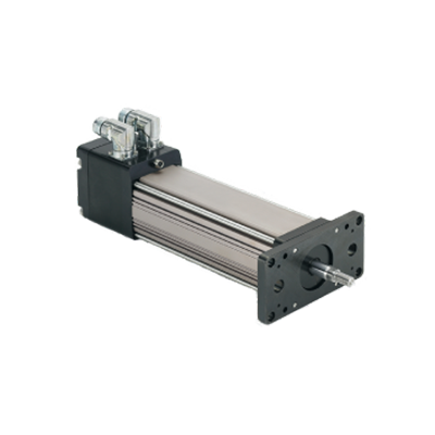
TRITEX I LINEAR
Fully Integrated Drive/Motor/Actuator
Industrial - Exlar
The Tritex I Linear is an Obsolete Product, No Longer Available. Need a comparable replacement, try our Tritex II AC or DC Linear actuators!
Industrial - Exlar
The Tritex I Linear is an Obsolete Product, No Longer Available. Need a comparable replacement, try our Tritex II AC or DC Linear actuators!
| Models: |
TLM20, TLM30, TSM20, TSM30 |
| Frame Sizes: |
2, 3 in (60, 80 mm) |
| Stroke Length: |
3, 6, 10, 12, 18 in (75, 150, 250, 305, 445 mm) |
| Screw Lead: |
0.1, 0.2, 0.4, 0.5 in (2, 5, 10, 13 mm) |
| Linear Speeds: |
up to 33.33 in/s (848 mm/s) |
| Continuous Thrust Capacity: |
Up to 1,545 lbf (Up to 6,872 N) |
| Standards/Ratings: |
UL Class 180H insulation, IP54S (IP65S optional) |
The option decriptions below are meant to be a reference only.
The Model TT232485 is a feature packed RS232 to RS-422/485 9-pin converter. It converts unbalanced, full or half duplex RS-232 signals to balanced, full or half-duplex RS422 or RS-485 signals at baud rates up to 115.2 kbps. In addition, the unit optically isolates and surge suppresses the RS-422/485 lines. The driver uses automatic SD (send data) or TS (handshake) control, or can be configured as always enabled for use in RS-422 systems.
A dipswitch selects communication features on the TT232485. Two LEDs show data traffic in either direction. Only one power supply is necessary, located on the RS-232 side. The isolated power and ground on the RS-422/485 side are generated internally.
Connections are made through a DB9 female connector on the RS-232 side and terminal blocks on the RS-422/485 side. All terminal blocks, dipswitches, and jumpers are located inside the hood and are reachable through the access panel, which slides closed to protect the connections.
The RS-232 port has a DB9 female connector with pins 3 (TD), 2 (RD), and 5 (Signal Ground) supported, pins 7 (RTS) and 8 (CTS) are tied together, and pins 6 (DSR), 1 (CD), and 4 (DTR), are also tied together. The 485OT9L has two LEDs: a Transmit Data LED showing when data goes from the RS-232 side to the RS-485 side, and a Receive Data LED showing data going from the RS-485 side to the RS-232 side. These are very useful for determining if data is getting through the converter. The RS-485 terminal blocks support Transmit Data (A) and (B), Receive Data (A) and (B), and Signal Ground. A single supply voltage of 10 to 30 VDC on the RS-232 side powers the unit. An 8-position dipswitch allows the selection of baud rate, 2-wire or 4-wire mode, echo on or off, and termination in or out.
Dip switches allow the module to be configured for two-wire or four-wire, RS-422 or RS-485 modes. In two-wire mode the TDA (-) and RDA (-) are tied together and so are TDB (+) and RDB (+), making multi-dropping this converter into an existing network easy.
|
Dip Switch Set-Up |
||
|---|---|---|
|
Switch |
Off |
On |
|
One |
TD always enabled |
TD only enabled during data transmission. (TD 485) |
|
Two |
RD always enabled (ECHO ON) |
RD disabled during data transmission. (ECHO OFF) |
|
Three |
Four-wire mode (4-Wire) |
Two-wire mode (2-Wire) |
|
Four |
Four-wire mode (4-Wire) |
Two-wire mode (2-Wire) |
Standard DC outputs 48 VDC, 10 Amps. 108/120/132/216/240/264 VAC input. The Model TTPS1048 unregulated power supply line is designed for high current applications at low cost when full regulation is not required. This rugged, highly reliable power supply line is ideal for applications such as powering solenoids, relays, DC motors, lamps and DC-DC converters. Standard DC outputs are listed below, other outputs from 9 to 175 volts are available on special order.
Bobbin Wound Transformer
Computer Grade Capacitors
Floating Output
Full Rated to 55 degrees Celsius
Open Frame Construction
Secondary Fuse Protection
AC Input 47-63 Hz
108/120/132/216/240/264 VAC Selection
Output Ripple: 3% RMS at full rated load, 4% on 12 volt model IP500U12
Efficiency @ Full Load 80% typical
UL Recognized for USA and Canada File Number E133338
TUV Rheinland licensed. Certificate no. R 9675002
Complies with the requirements of standard EN 60590 and low voltage directive 72/23/EEC
No Load Voltage: 56.6
Half Load Voltage: 52.8
Full Load Voltage: 48.8
Full Load Amps: 10
The TT232485 uses either RTS Control or Send Data Control to enable the RS-485 driver. This option is user selectable by setting push-on jumpers located next to the terminal blocks. RTS controls the driver using toggling Request to Send (pin 7) of the RS-232 side. Raising RTS enables the driver and lowering RTS disables it. Automatic Send Data Control recognizes the first bit of data from the RS-232 side, enables the transmitter and disables the receiver. After the last bit of data is sent from the RS-232 side, the TT232485 waits one character length then disables the transmitter and enables the receiver. The timeout can be selected with dipswitches or by changing the value of R21 (see Table, Baud Rate Selection). The timeout is preset at the factory for 9600 baud. Removing both sets of jumpers completely will constantly enable the RS-485 driver. This makes the TT232485 behave like an RS-422 converter. For settings, see Table, Standard Communications Settings.
No special software is required to control the RS-485 receiver or transmit line driver. The driver is automatically enabled during each byte transmitted in RS-485 mode. The transmitter is always enabled in RS-422 mode. The receiver is tri-stated during each byte transmitted in the echo-off mode. The receiver is always enabled in the echo-on mode. There are 4.7k Ohm pull-down resistors on the RDA and RDB lines. A termination resistor may be added to R16 if needed.
Termination resistance can be selected with Switch 8 for high baud rates and long cable distances. The 4-wire/2-wire switches (6 and 7) are turned off for 4-wire mode and on for 2-wire mode. When they are set on, they connect TD(A) to RD(A) and TD(B) to RD(B) internally. Switch 5 controls Echo on and off. When switch 5 is in the off position the receiver is constantly enabled. Placing the switch in the on position allows the driver or the receiver to be enabled at any time. In 2-wire mode it is recommended that switch 5 be turned on to prevent data being set out from “echoing” back through the receiver. Up to 32 receivers can be driven by any one RS-485 driver, allowing you to put together large systems with many drop points.
|
BAUD RATE SELECTION |
||||||
|---|---|---|---|---|---|---|
|
Baud |
Switch 1 |
Switch 2 |
Switch 3 |
Switch 4 |
R21 |
Time out (ms) |
|
1200 |
OFF |
OFF |
OFF |
OFF |
820kOhms |
9.0 |
|
2400 |
OFF |
OFF |
OFF |
OFF |
410kOhms |
4.5 |
|
4800 |
ON |
OFF |
OFF |
OFF |
Not Used |
2.2 |
|
9600 |
OFF |
ON |
OFF |
OFF |
Not Used |
1.1 |
|
19200 |
OFF |
OFF |
ON |
OFF |
Not Used |
0.6 |
|
38400 |
OFF |
OFF |
OFF |
ON |
Not Used |
0.3 |
|
57600 |
OFF |
OFF |
ON |
ON |
Not Used |
0.2 |
|
115200 |
OFF |
OFF |
OFF |
OFF |
8.2kOhms |
0.1 |
Transient over voltage problems are quickly solved using shunt regulators that clamp regeneration voltage to safe levels. These simple devices can increase system reliability by stabilizing voltage fluctuations and eliminate over-voltage shutdowns.
The purpose of a shunt regulator is to ‘burn off’ excess regeneration energy that is produced when a drive brings a large load to a stop. Mechanical braking systems use friction to stop a load and convert kinetic energy into heat. Servo drives on the other hand are very efficient power converters – typically over 98%! They convert electrical energy from the motor to the power supply just as efficiently as when they convert energy from the power supply to the motor. During a rapid deceleration or the deceleration of a large load, enough excess energy can be transferred to shut down the drive or damage the power supply.
A shunt regulator ‘clamps’ the power supply voltage to a set level and prevents unexpected shutdown or damage. It monitors the power supply voltage and if the voltage exceeds the set limit, the shunt regulator ‘bleeds off’ the extra voltage through a power resistor. The shunt regulator is only active when the voltage exceeds the set level; otherwise, no current passes through the power resistor. The shunt regulator automatically turns the power resistor on and off as necessary to regulate the voltage, sometimes up to several hundred Hertz.
The TTSR1 shunt regulator is designed to work with four quadrant regenerative servo amplifiers. During braking most of the stored mechanical energy is fed back into the power supply, which charges the output capacitor to a higher voltage. If the charge reaches the amplifier’s over-voltage shutdown point, motor control and braking will cease. To ensure smooth braking of large inertial loads with use of a shunt regulator is recommended. Verify the need for a shunt regulator by operating the servo under the worst case braking condition. If the amplifier shuts off due to over-voltage (blinking red LED) a shunt regulator is necessary (typically during downward move or deceleration).
When the DC bus reaches the shunt voltage of the shunt-regulator assembly, the voltage comparator unit turns on the electronic switch, which connects the R1 power resistor across the DC bus. This power resistor dissipates the energy from the DC bus. After the bus voltage is reduced to less than the shunt voltage setting the resistor is disconnected from the bus. A small hysteresis loop allows time between switching. The TTSR1 assembly is available with standard shunt voltages of 50, 70, 80, 90, 135, 175, 185, 380 and 400 Volts.
Fuse: 3A motor delay rated @ 250 VAC
Filter Capacitance: 1200 microF
Dissipation Capabilities: 95W
Resistance: 5 Ohms
Size: 8.00 x 4.25 x 2.63 inches (203.2 x 108.0 x 66.7 mm)
Weight: .32 lbs (.14 kg)
RS485 Communications splitter. Use to daisy-chain multiple Tritex actuators.
|
Standard Communications Settings |
||||
|---|---|---|---|---|
|
Communication Mode |
JP1 |
Switch 5 |
Switch 6 |
Switch 7 |
|
RS-422 Mode (full duplex) |
Neither |
OFF |
OFF |
OFF |
|
RS-485 4-Wire Mode |
RTS or SD |
OFF |
OFF |
OFF |
|
RS-485 2-Wire Mode |
RTS or SD |
ON |
ON |
ON |
Supporting 2-wire RS-485 or a 4-wire RS-422/485 communications, this device is well suited for any application that requires long range or multi-drop capabilities. The TTUSB485 model uses pluggable terminal blocks on the RS-422/485 side and has a pair of LEDs that indicate data being transmitted or received. Model TTUSB485 includes special circuitry that adds 2000 volts isolation protection against ground loops and voltage spikes; and it draws power from the USB port so no power supplies is required.
Simply plug the converter into an available USB port on your computer or USB hub and the device will show up as an additional COM port in the Windows Device Manager. Configured as an additional COM port, the converter is now compatible with your Windows applications.
Universal Serial Bus (USB) has become the connectivity workhorse of today’s PCs, replacing the familiar serial ports. But many commercial and industrial devices still use RS-422/485 interfaces. To connect these devices to modern PCs you need robust and reliable conversion solutions. At the same time, USB ports are becoming more common on commercial and industrial equipment such as point-of-sale peripherals, medical devices, scientific instrumentation, laboratory equipment and other devices. Sometimes these are used in environments where surges, spikes and ground loops are likely to occur.
|
Back to Top
|
TLM20 Performance Specifications |
||||
|---|---|---|---|---|
|
Backlash in (mm) |
.008 (.20) |
|||
|
Lead Accuracy in/ft (mm/300 mm) |
.001 (.025) |
|||
|
Maximum Radial Load lb (N) |
15 (67) |
|||
|
Environmental Rating: Std |
IP54 / IP65 Optional |
|||
|
Stator |
1 Stack 1B8-50 |
2 Stack 2B8-34 |
3 Stack 3B8-25 |
|
|
Lead RPM at 48 VDC* |
5000 |
3400 |
2500 |
|
|
Stall Force lbf (N) |
|
239 (1063) |
377 (1677) |
503 (2237) |
|
0.1 |
Max Speed in/sec (mm/sec) |
8.33 (212) |
5.66 (144) |
4.17 (106) |
|
Stall Force lbf (N) |
119 (529) |
188 (836) |
251 (1117) |
|
|
0.2
|
Max Speed in/sec (mm/sec) |
16.66 (424) |
11.33 (288) |
8.33 (212) |
|
Stall Force lbf (N) |
60 (267) |
94 (418) |
126 (560) |
|
|
0.4 |
Max Speed in/sec (m/sec) |
33.33 (848) |
22.66 (575) |
16.66 (424) |
|
Power Supply Current Draw at Rated Power (48 V) |
Amps |
10 |
10 |
10 |
|
Resolution Accuracy (not including backlash) |
0.001 revolution x lead +/- 0.005 revolution x lead |
|||
|
Stroke Length inch (mm) |
3 (75) |
6 (150) |
10 (250) |
12 (305) |
|
Approximate Weight lb (kg) |
7 (3.2) |
8.5 (3.9) |
10 (4.5) |
11.5 (5.2) |
*RPM @ 24 VDC = 1/2 of listed value
Printable view
|
TLM30 Performance Specifications |
||||||
|---|---|---|---|---|---|---|
|
Backlash in (mm) |
.008 (.20) |
|||||
|
Lead Accuracy in/ft (mm/300 mm) |
.001 (.025) |
|||||
|
Maximum Radial Load lb (N) |
20 (90) |
|||||
|
Environmental Rating: Std |
IP54 |
|||||
|
STATOR |
1 Stack 1B8-20 |
2 Stack 2B8-13 |
3 Stack 3B8-10 |
|||
|
Lead |
RPM at 48 VDC* |
2000 |
1300 |
1000 |
||
|
0.1 |
Stall Force |
lbf (N) |
585 (2606) |
935 (4159) |
1250 (5560) |
|
|
Max Speed |
in/sec (mm/sec) |
3.33 (84.6) |
2.17 (55.1) |
1.67 (42.4) |
||
|
0.2 |
Stall Force |
lbf (N) |
293 (1303) |
468 (2082) |
625 (2780) |
|
|
Max Speed |
in/sec (mm/sec) |
6.67 (169.4) |
4.33 (109.9) |
3.33 (84.6) |
||
|
0.5 |
Stall Force |
lbf (N) |
117 (520) |
187 (832) |
250 (1112) |
|
|
Max Speed |
in/sec (m/sec) |
16.67 (423.4) |
10.83 (275.1) |
8.33 (211.6) |
||
|
Power Supply Current Draw at Rated Power |
Amps |
10 |
10 |
10 |
||
|
Resolution Accuracy (not including backlash) |
0.001 revolution x lead +/- 0.005 revolution x lead |
|||||
|
Stroke Length inch (mm) |
3 (75) |
6 (150) |
10 (250) |
12 (305) |
18 (455) |
|
|
Approximate Weight lb (kg) |
10 (4.5) |
12 (5.4) |
19.5 (8.8) |
21 (9.5) |
25.5 (11.6) |
|
*RPM @ 24 VDC = 1/2 of listed value
Printable view
|
TSM20 Performance Specifications |
||||||||||
|---|---|---|---|---|---|---|---|---|---|---|
|
Backlash in (mm) |
.008 (.20) |
|||||||||
|
Lead Accuracy in/ft (mm/300 mm) |
.001 (.025) |
|||||||||
|
Maximum Radial Load lb (N) |
15 (67) |
|||||||||
|
Environmental Rating: Std |
IP54 / IP65 Optional |
|||||||||
|
Stator |
1 Stack 1B8-50 |
2 Stack 2B8-34 |
3 Stack 3B8-25 |
|||||||
|
RPM at 48 VDC* |
5000 |
3400 |
2500 |
|||||||
|
Lead Ambient Temp |
25 |
40 |
55 |
25 |
40 |
55 |
25 |
40 |
55 |
|
|
0.1 |
Stall Force lbf |
295 |
262 |
227 |
460 |
411 |
355 |
575 |
514 |
445 |
| (N) |
(1312) |
(1165) |
(1010) |
(2046) |
(1828) |
(1579) |
(2558) |
(2286) |
(1979) |
|
| Max Speed in/sec (mm/sec) |
8.33 (212) |
5.66 (144) |
4.17 (106) |
|||||||
|
0.2 |
Stall Force lbf |
148 |
131 |
113 |
230 |
205 |
177 |
288 |
257 |
223 |
| (N) |
(658) |
(583) |
(503) |
(1023) |
(912) |
(787) |
(1281) |
(1143) |
(992) |
|
| Max Speed in/sec (mm/sec) |
16.66 (424) |
11.33 (288) |
8.33 (212) |
|||||||
|
0.4 |
Stall Force lbf |
74 |
66 |
57 |
92 |
82 |
71 |
115 |
103 |
89 |
| (N) |
(329) |
(294) |
(254) |
(409) |
(365) |
(316) |
(512) |
(458) |
(396) |
|
| Max Speed in/sec (m/sec) |
33.33 (848) |
22.66 (575) |
16.66 (424) |
|||||||
|
Power Supply Current |
10 |
10 |
10 |
|||||||
|
Resolution |
0.001 revolution x lead |
|||||||||
|
Accuracy (not including backlash) |
+/- 0.005 revolution x lead |
|||||||||
|
Stroke Length inch (mm) |
3 (75) |
6 (150) |
10 (250) |
12 (305) |
||||||
|
Approximate Weight lb (kg) |
7 (3.2) |
8.5 (3.9) |
10 (4.5) |
11.5 (5.2) |
||||||
*RPM @ 24 VDC = 1/2 of listed value
Printable view
|
TSM30 Performance Specifications |
|||||||||||
|---|---|---|---|---|---|---|---|---|---|---|---|
|
Backlash in (mm) |
.008 (.20) |
||||||||||
|
Lead Accuracy in/ft (mm/300 mm) |
.001 (.025) |
||||||||||
|
Maximum Radial Load lb (N) |
20 (90) |
||||||||||
|
Environmental Rating: Std |
IP54/ IP65 Optional |
||||||||||
|
STATOR |
1 Stack 1B8-20 |
2 Stack 2B8-13 |
3 Stack 3B8-10 |
||||||||
|
RPM at 48 VDC* |
2000 |
1300 |
1000 |
||||||||
|
Lead Ambient Temp |
Degrees C |
25 |
40 |
55 |
25 |
40 |
55 |
25 |
40 |
55 |
|
|
0.1 |
Stall Force |
lbf (N) |
756 |
686 |
608 |
1201 |
1091 |
968 |
1545 |
1404 |
1247 |
|
Max Speed |
in/sec (mm/sec) |
3.33 (84.6) |
2.17 (55.1) |
1.67 (42.4) |
|||||||
|
0.2 |
Stall Force |
lbf (N) |
378 |
343 |
304 |
600 |
545 |
484 |
772 |
702 |
623 |
|
Max Speed |
in/sec (mm/sec) |
6.67 (169.4) |
4.33 (109.9) |
3.33 (84.6) |
|||||||
|
0.5 |
Stall Force |
lbf (N) |
151 |
137 |
122 |
240 |
218 |
194 |
309 |
281 |
249 |
|
Max Speed |
in/sec (m/sec) |
16.67 (423.4) |
10.83 (275.1) |
8.33 (211.6) |
|||||||
|
Power Supply Current Draw at Rated Power (48 V) |
Amps |
15 |
12 |
10 |
15 |
12 |
10 |
15 |
12 |
10 |
|
|
Resolution Accuracy (not including backlash) |
0.001 revolution x lead +/- 0.005 revolution x lead |
||||||||||
|
Stroke Length inch (mm) |
3 (75) |
6 (150) |
10 (250) |
12 (305) |
18 (445) |
||||||
|
Approximate Weight lb (kg) |
10 (4.5) |
12 (5.4) |
19.5 (8.8) |
21 (9.5) |
25.5 (11.6) |
||||||
|
Dynamic Load Rating lb (N) |
.1 inch lead 1568 (6970) .2 inch lead 1219 (5422) .4 inch lead 738 (3283) |
||||||||||
|
Estimated Travel Life |
Travel life in millions of inches where C = Dynamic load rating (lbf), F = Cubic mean applied load (lbf) and S = Roller screw’s lead (inch). L = (C/F)³ x S = |
||||||||||
*RPM @ 24 VDC = 1/2 of listed value
Printable view

