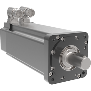
SLM Series Rotary Actuators
Brushless Servo Motor
Industrial - Exlar
Industrial - Exlar
| Models | Frame Size mm (in) | Max Continuous Torque Nm (lbf-in) | Max Speed RPM |
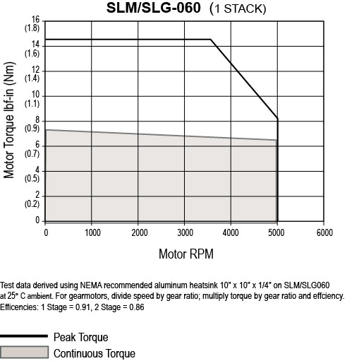
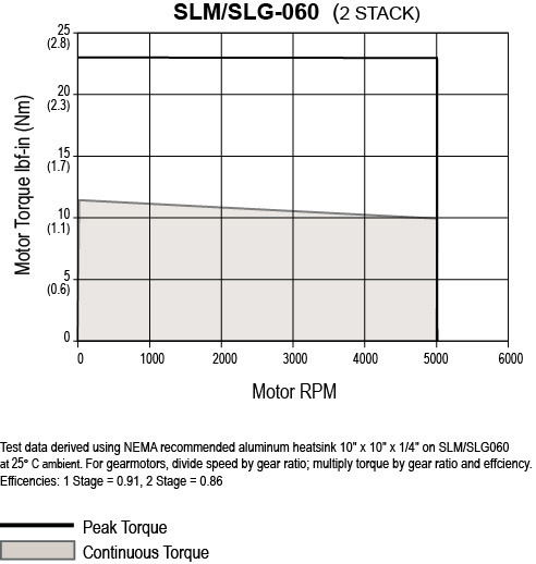
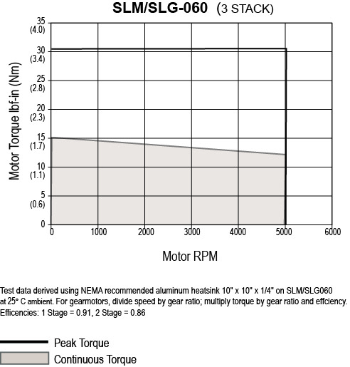
| SLM060 | 60 (2.36) | 1.73 (15.3) | 5000 |
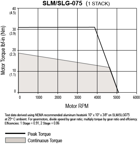
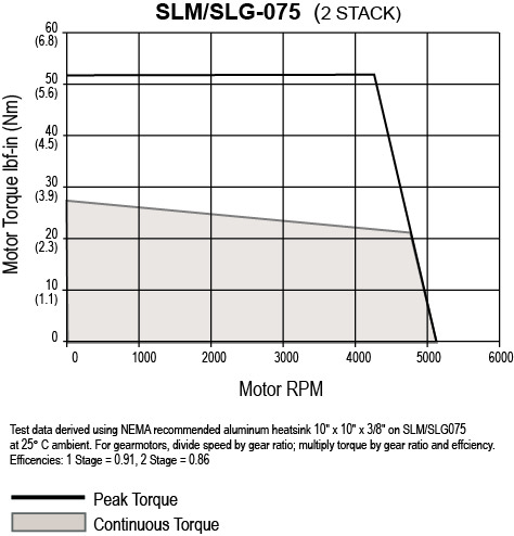
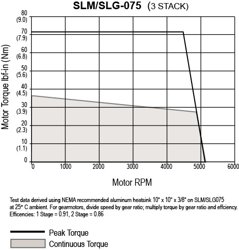
| SLM075 | 75 (2.95) | 4.29 (37.9) | 4000 |
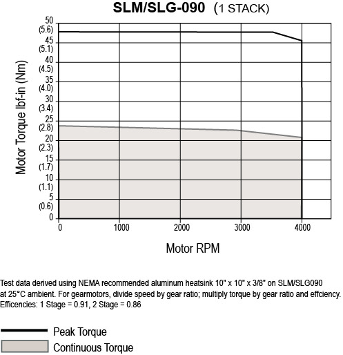
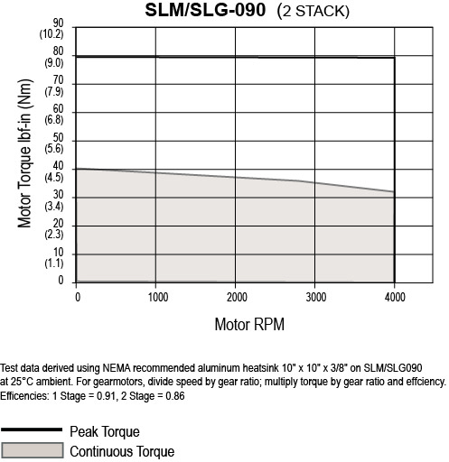
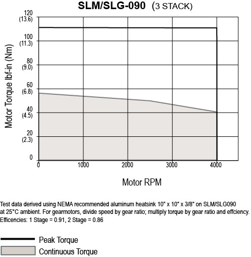
| SLM090 | 90 (3.54) | 6.3 (55.7) | 4000 |
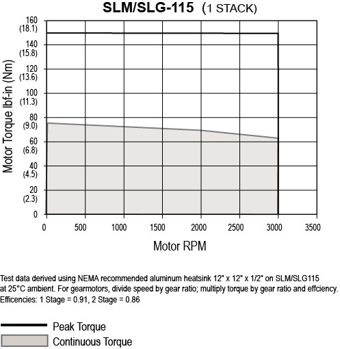
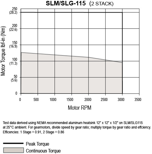
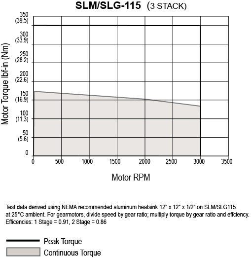
| SLM115 | 115 (4.53) | 19.98 (176.9) | 3000 |
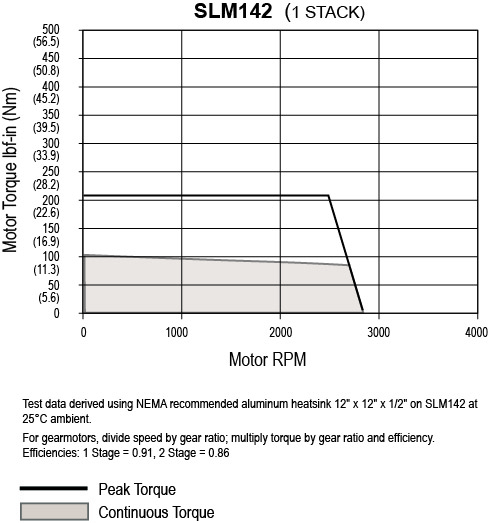
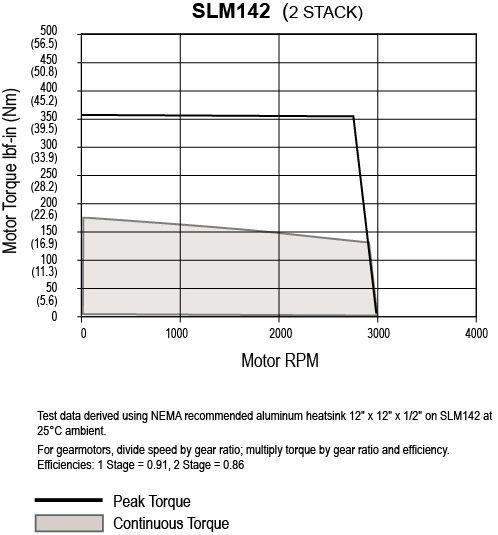
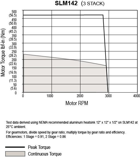
| SLM142 | 142 (5.59) | 26.93 (238.3) | 2400 |
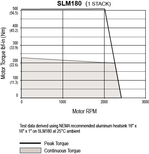
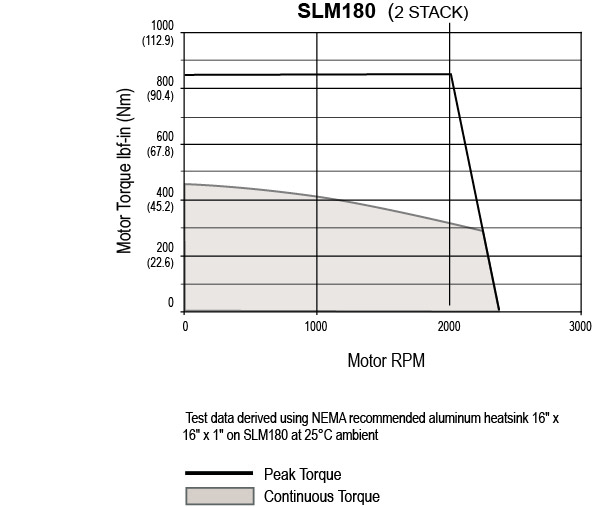
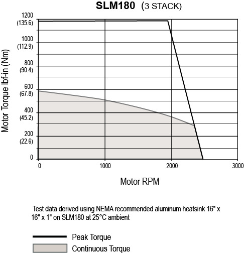
| SLM180 | 180 (7.10) | 69.1 (611.6) | 2400 |
Brushless servo motor technology from Exlar® provides high torque and a small package size. Available in 60 to 180 mm frame sizes with 1, 2, or 3 stack lengths in 8 pole configuration, these compact motors pack a powerful punch.
Standard configurations include:
The innovative T-LAM™ segmented lamination stator design increases power without increasing size. Each segment contains individual phase wiring for maximum motor performance. Robust insulation, high coercive strength magnets, and complete thermal potting are integrated to create a more powerful and efficient motor. The design yields 35 to 70% more torque from the same size package. Also, T-LAM designs feature Class 180H insulation and UL recognition.
Other Brushless Servo Motor Advantages

-Order.jpg)
|
G = Model Series |
E = Coating Options |
NOTES:
1. Available as described in Feedback Types.
2. See catalog for explanation of voltage, speed, stack and optimized stator options.
* Some options are not available with every configuration. For options or specials not listed above contact your local Exlar representative.
|
SLM/G = Model Series |
E = Coating Options1 |
NOTES:
1. These housing may indicate the need for special material main rods or mounting.
2. 115 Vrms is not available on a 2 or 3 stack SLM/G, or a 3 stack SLM/G090.
* Some options are not available with every configuration. For options or specials not listed above contact your local Exlar representative.
|
Back to Top
| Motor Stacks | 118 | 138 | 158 | 168 | 218 | 238 | 258 | 268 | 318 | 338 | 358 | 368 | |
|---|---|---|---|---|---|---|---|---|---|---|---|---|---|
| Voltage Rating | Vrms | 115 | 230 | 400 | 460 | 115 | 230 | 400 | 460 | 115 | 230 | 400 | 460 |
| Speed @ Bus Voltage | rpm | 5000 | 5000 | 5000 | 5000 | 5000 | 5000 | 5000 | 5000 | 5000 | 5000 | 5000 | 5000 |
| Sinusoidal Commutation Data | |||||||||||||
| Continuous Motor Torque | lbf-in | 7.6 | 7.3 | 7 | 7 | 11.9 | 11.5 | 11 | 11.3 | 15 | 15.3 | 14.6 | 14.9 |
| Nm | 0.86 | 0.83 | 0.79 | 0.79 | 1.34 | 1.3 | 1.25 | 1.28 | 1.7 | 1.73 | 1.65 | 1.69 | |
| Peak Motor Torque | lbf-in | 15.2 | 14.7 | 14 | 14 | 23.8 | 23 | 22.1 | 22.6 | 30 | 30.6 | 29.2 | 29.9 |
| Nm | 1.72 | 1.66 | 1.58 | 1.58 | 2.69 | 2.6 | 2.49 | 2.55 | 3.39 | 3.46 | 3.3 | 3.38 | |
| Torque Constant (Kt) (+/– 10% @ 25˚C) | lbf-in/A | 2.5 | 5.2 | 7.5 | 9.5 | 2.5 | 5.2 | 8.6 | 10.1 | 2.5 | 5.3 | 8.8 | 10.1 |
| Nm/A | 0.28 | 0.6 | 0.9 | 1.1 | 0.3 | 0.6 | 1 | 1.1 | 0.3 | 0.6 | 1 | 1.1 | |
| Continuous Current Rating | A | 3.4 | 1.6 | 1 | 0.8 | 5.4 | 2.5 | 1.4 | 1.2 | 6.6 | 3.2 | 1.9 | 1.6 |
| Peak Current Rating | A | 6.9 | 3.1 | 2 | 1.6 | 10.8 | 4.9 | 2.9 | 2.5 | 13.2 | 6.5 | 3.7 | 3.3 |
| O-PK Sinusoidal Commutation Data | |||||||||||||
| Continuous Motor Torque | lbf-in | 7.6 | 7.3 | 7 | 7 | 11.9 | 11.5 | 11 | 11.3 | 15 | 15.3 | 14.6 | 14.9 |
| Nm | 0.86 | 0.83 | 0.79 | 0.79 | 1.34 | 1.3 | 1.25 | 1.28 | 1.7 | 1.73 | 1.65 | 1.69 | |
| Peak Motor Torque | lbf-in | 15.2 | 14.7 | 14 | 14 | 23.8 | 23 | 22.1 | 22.6 | 30 | 30.6 | 29.2 | 29.9 |
| Nm | 1.72 | 1.66 | 1.58 | 1.58 | 2.69 | 2.6 | 2.49 | 2.55 | 3.39 | 3.46 | 3.3 | 3.38 | |
| Torque Constant (Kt) (+/– 10% @ 25˚C) | lbf-in/A | 1.7 | 3.7 | 5.3 | 6.7 | 1.7 | 3.7 | 6.1 | 7.2 | 1.8 | 3.7 | 6.2 | 7.2 |
| Nm/A | 0.2 | 0.4 | 0.6 | 0.8 | 0.2 | 0.4 | 0.7 | 0.8 | 0.2 | 0.4 | 0.7 | 0.8 | |
| Continuous Current Rating | A | 4.9 | 2.2 | 1.5 | 1.2 | 7.6 | 3.5 | 2 | 1.8 | 9.4 | 4.6 | 2.6 | 2.3 |
| Peak Current Rating | A | 9.7 | 4.5 | 2.9 | 2.3 | 15.2 | 7 | 4.1 | 3.5 | 18.7 | 9.2 | 5.3 | 4.7 |
| Motor Data | |||||||||||||
| Voltage Constant (Ke) (+/– 10% @ 25˚C) | Vrms/Krpm | 16.9 | 35.5 | 51.5 | 64.8 | 16.9 | 35.5 | 58.6 | 69.3 | 17.3 | 36 | 59.9 | 69.3 |
| Vpk/Krpm | 23.9 | 50.2 | 72.8 | 91.7 | 23.9 | 50.2 | 82.9 | 98 | 24.5 | 50.9 | 84.8 | 98 | |
| Pole Configuration | 8 | 8 | 8 | 8 | 8 | 8 | 8 | 8 | 8 | 8 | 8 | 8 | |
| Resistance (L-L) (+/– 5% @ 25˚C) | Ohms | 2.6 | 12.52 | 28.82 | 45.79 | 1.11 | 5.26 | 15.51 | 20.69 | 0.76 | 3.14 | 9.57 | 12.22 |
| Inductance (L-L) (+/– 15%) | mH | 4.6 | 21.4 | 47.9 | 68.3 | 2.5 | 10.2 | 28.3 | 39.5 | 1.7 | 7.4 | 18.5 | 27.4 |
| SLM Armature Inertia (+/– 5%) | bf-in-sec^2 | 0.000237 | 0.000413 | 0.000589 | |||||||||
| Kg-cm^2 | 0.268 | 0.466 | 0.665 | ||||||||||
| Brake Inertia | lbf-in-sec^2 | 0.00012 | |||||||||||
| Kg-cm^2 | 0.135 | ||||||||||||
| Brake Current @ 24 VDC | A | 0.33 | 0.33 | 0.33 | 0.33 | 0.33 | 0.33 | 0.33 | 0.33 | 0.33 | 0.33 | 0.33 | 0.33 |
| Brake Holding Torque | lbf-in | 19 | 19 | 19 | 19 | 19 | 19 | 19 | 19 | 19 | 19 | 19 | 19 |
| Nm | 2.2 | 2.2 | 2.2 | 2.2 | 2.2 | 2.2 | 2.2 | 2.2 | 2.2 | 2.2 | 2.2 | 2.2 | |
| Brake Engage/Disengage Time | ms | 14/28 | 14/28 | 14/28 | 14/28 | 14/28 | 14/28 | 14/28 | 14/28 | 14/28 | 14/28 | 14/28 | 14/28 |
| Mechanical Time Constant (tm) | ms | 2.2 | 2.38 | 2.6 | 2.61 | 1.62 | 1.74 | 1.89 | 1.8 | 1.5 | 1.45 | 1.59 | 1.52 |
| Electrical Time Constant (te) | ms | 1.76 | 1.71 | 1.66 | 1.49 | 2.24 | 1.95 | 1.82 | 1.91 | 2.27 | 2.36 | 1.93 | 2.24 |
| Friction Torque | lbf-in (Nm) | 0.27 (0.031) | 0.27 (0.031) | 0.27 (0.031) | 0.27 (0.031) | 0.34 (0.038) | 0.34 (0.038) | 0.34 (0.038) | 0.34 (0.038) | 0.38 (0.043) | 0.38 (0.043) | 0.38 (0.043) | 0.38 (0.043) |
| Insulation Class | 180 (H) | 180 (H) | 180 (H) | 180 (H) | 180 (H) | 180 (H) | 180 (H) | 180 (H) | 180 (H) | 180 (H) | 180 (H) | 180 (H) | |
| Insulation System Volt Rating | Vrms | 460 | 460 | 460 | 460 | 460 | 460 | 460 | 460 | 460 | 460 | 460 | 460 |
| Environmental Rating | IP65S | IP65S | IP65S | IP65S | IP65S | IP65S | IP65S | IP65S | IP65S | IP65S | IP65S | IP65S | |
Printable view
| Motor Stacks | 118 | 138 | 158 | 168 | 218 | 238 | 258 | 268 | 318 | 338 | 358 | 368 | |
|---|---|---|---|---|---|---|---|---|---|---|---|---|---|
| Voltage Rating | Vrms | 115 | 230 | 400 | 460 | 115 | 230 | 400 | 460 | 115 | 230 | 400 | 460 |
| Speed @ Bus Voltage | rpm | 4000 | 4000 | 4000 | 4000 | 4000 | 4000 | 4000 | 4000 | 4000 | 4000 | 4000 | 4000 |
| RMS Sinusoidal Commutation | |||||||||||||
| Continuous Motor Torque | lbf-in | 16.6 | 16.4 | 16.3 | 16 | 26 | 26.4 | 26.2 | 26.4 | 37.9 | 35.9 | 37.3 | 36.4 |
| Nm | 1.88 | 1.85 | 1.84 | 1.81 | 2.94 | 2.89 | 2.96 | 2.98 | 4.29 | 4.05 | 4.21 | 4.12 | |
| Peak Motor Torque | lbf-in | 33.3 | 32.8 | 32.6 | 32.1 | 52 | 52.7 | 52.4 | 52.8 | 75.9 | 71.7 | 74.6 | 72.9 |
| Nm | 3.76 | 3.7 | 3.68 | 3.62 | 5.88 | 5.96 | 5.92 | 5.96 | 8.57 | 8.1 | 8.43 | 8.23 | |
| Torque Constant (Kt) (+/– 10% @ 25˚C) | lbf-in/A | 3.4 | 6.6 | 12.5 | 13.1 | 3.7 | 6.8 | 11.6 | 13.5 | 3.4 | 6.8 | 11.6 | 13.9 |
| Nm/A | 0.4 | 0.7 | 1.4 | 1.5 | 0.4 | 0.8 | 1.3 | 1.5 | 0.4 | 0.8 | 1.3 | 1.6 | |
| Continuous Current Rating | A | 5.5 | 2.8 | 1.5 | 1.4 | 7.9 | 4.4 | 2.5 | 2.2 | 12.5 | 5.9 | 3.6 | 2.9 |
| Peak Current Rating | A | 11 | 5.6 | 2.9 | 2.7 | 15.9 | 8.7 | 5.1 | 4.4 | 25.1 | 11.8 | 7.2 | 5.8 |
| O-PeaK Sinusoidal Commutation | |||||||||||||
| Continuous Motor Torque | lbf-in | 16.6 | 16.4 | 16.3 | 16 | 26 | 26.4 | 26.2 | 26.4 | 37.9 | 35.9 | 37.3 | 36.4 |
| Nm | 1.88 | 1.85 | 1.84 | 1.81 | 2.94 | 2.98 | 2.96 | 2.98 | 4.29 | 4.05 | 4.21 | 4.12 | |
| Peak Motor Torque | lbf-in | 33.3 | 32.8 | 32.6 | 32.1 | 52 | 52.7 | 52.4 | 52.8 | 75.9 | 71.7 | 74.6 | 72.9 |
| Nm | 3.76 | 3.7 | 3.68 | 3.62 | 5.88 | 5.96 | 5.92 | 5.96 | 8.57 | 8.1 | 8.43 | 8.23 | |
| Torque Constant (Kt) (+/– 10% @ 25˚C) | lbf-in/A | 2.4 | 4.6 | 8.8 | 9.3 | 2.6 | 4.8 | 8.2 | 9.6 | 2.4 | 4.8 | 8.2 | 9.9 |
| Nm/A | 0.3 | 0.5 | 1 | 1 | 0.3 | 0.5 | 0.9 | 1.1 | 0.3 | 0.5 | 0.9 | 1.1 | |
| Continuous Current Rating | A | 7.8 | 4 | 2.1 | 1.9 | 11.2 | 6.2 | 3.6 | 3.1 | 17.7 | 8.4 | 5.1 | 4.1 |
| Peak Current Rating | A | 15.6 | 7.9 | 4.1 | 3.9 | 22.4 | 12.3 | 7.2 | 6.2 | 35.5 | 16.8 | 10.1 | 8.3 |
| Motor stator Data | |||||||||||||
| Voltage Constant (Ke) (+/– 10% @ 25˚C) | Vrms/Krpm | 23.1 | 44.7 | 85.2 | 89.5 | 25 | 46.2 | 78.9 | 92.4 | 23.1 | 46.2 | 79.4 | 95.3 |
| Vpk/Krpm | 32.7 | 63.3 | 120.4 | 126.5 | 35.4 | 65.3 | 111.6 | 130.6 | 32.7 | 65.3 | 112.3 | 134.7 | |
| Pole Configuration | 8 | 8 | 8 | 8 | 8 | 8 | 8 | 8 | 8 | 8 | 8 | 8 | |
| Resistance (L-L)(+/– 5% @ 25˚C) | Ohms | 1.66 | 6.42 | 23.49 | 26.84 | 0.83 | 2.75 | 8.15 | 11.01 | 0.4 | 1.77 | 4.83 | 7.29 |
| Inductance (L-L)(+/– 15%) | mH | 4.6 | 17.3 | 62.6 | 69.2 | 2.6 | 8.8 | 25.7 | 35.2 | 1.4 | 5.8 | 17 | 24.5 |
| SLM Armature Inertia | lbf-in-sec^2 (+/– 5%) | 0.00054 | 0.00097 | 0.0014 | |||||||||
| Kg-cm^2 | 0.616 | 1.1 | 1.583 | ||||||||||
| Brake Inertia | lbf-in-sec^2 | 0.000159 | |||||||||||
| Kg-cm^2 | 0.18 | ||||||||||||
| Brake Current @ 25 VDC | A | 0.5 | 0.5 | 0.5 | 0.5 | 0.5 | 0.5 | 0.5 | 0.5 | 0.5 | 0.5 | 0.5 | 0.5 |
| Brake Holding Torque | lbf-in | 40 | 40 | 40 | 40 | 40 | 40 | 40 | 40 | 40 | 40 | 40 | 40 |
| Nm | 4.5 | 4.5 | 4.5 | 4.5 | 4.5 | 4.5 | 4.5 | 4.5 | 4.5 | 4.5 | 4.5 | 4.5 | |
| Brake Engage/Disengage Time | ms | 9/35 | 9/35 | 9/35 | 9/35 | 9/35 | 9/35 | 9/35 | 9/35 | 9/35 | 9/35 | 9/35 | 9/35 |
| Mechanical Time Constant (tm) | ms | 1.71 | 1.77 | 1.79 | 1.85 | 1.31 | 1.27 | 1.29 | 1.27 | 1.05 | 1.18 | 1.09 | 1.14 |
| Electrical Time Constant (te) | ms | 2.78 | 2.69 | 2.67 | 2.58 | 3.11 | 3.19 | 3.15 | 3.2 | 3.65 | 3.26 | 3.53 | 3.37 |
| Friction Torque | lbf-in (Nm) | 0.51 (0.058) | 0.51 (0.058) | 0.51 (0.058) | 0.51 (0.058) | 0.67 (0.075) | 0.67 (0.075) | 0.67 (0.075) | 0.67 (0.075) | 0.90 (0.101) | 0.90 (0.101) | 0.90 (0.101) | 0.90 (0.101) |
| Insulation Class | 180 (H) | 180 (H) | 180 (H) | 180 (H) | 180 (H) | 180 (H) | 180 (H) | 180 (H) | 180 (H) | 180 (H) | 180 (H) | 180 (H) | |
| Insulation System Volt Rating | Vrms | 460 | 460 | 460 | 460 | 460 | 460 | 460 | 460 | 460 | 460 | 460 | 460 |
| Environmental Rating | IP65S | IP65S | IP65S | IP65S | IP65S | IP65S | IP65S | IP65S | IP65S | IP65S | IP65S | IP65S | |
For amplifiers using peak sinusoidal ratings, multiply RMS sinusoidal Kt by 0.707 and current by 1.414.
Printable view
| Motor Stacks | 118 | 138 | 158 | 168 | 218 | 238 | 258 | 268 | 338 | 358 | 368 | |
|---|---|---|---|---|---|---|---|---|---|---|---|---|
| Voltage Rating | Vrms | 115 | 230 | 400 | 460 | 115 | 230 | 400 | 460 | 230 | 400 | 460 |
| Speed @ Bus Voltage | rpm | 4000 | 4000 | 4000 | 4000 | 4000 | 4000 | 4000 | 4000 | 4000 | 4000 | 4000 |
| Sinusoidal Commutation Data | ||||||||||||
| Continuous Motor Torque | lbf-in | 23.8 | 24 | 23.7 | 24.7 | 39.6 | 40 | 39.5 | 39.9 | 55.7 | 55.4 | 55.7 |
| Nm | 2.68 | 2.71 | 2.67 | 2.79 | 4.47 | 4.52 | 4.46 | 4.51 | 6.3 | 6.26 | 6.3 | |
| Peak Motor Torque | lbf-in | 47.5 | 48 | 47.3 | 49.4 | 79.1 | 80 | 79 | 79.9 | 111.5 | 110.9 | 111.5 |
| Nm | 5.37 | 5.42 | 5.35 | 5.58 | 8.94 | 9.04 | 8.93 | 9.02 | 12.59 | 12.52 | 12.59 | |
| Torque Constant (Kt) (+/– 10% @ 25˚C) | lbf-in/A | 3.2 | 6.6 | 11.6 | 13.2 | 3.2 | 6.6 | 11.6 | 13.2 | 6.6 | 11.6 | 13.1 |
| Nm/A | 0.37 | 0.7 | 1.3 | 1.5 | 0.4 | 0.7 | 1.3 | 1.5 | 0.7 | 1.3 | 1.5 | |
| Continuous Current Rating | A | 8.2 | 4 | 2.3 | 2.1 | 13.6 | 6.8 | 3.8 | 3.4 | 9.5 | 5.3 | 4.8 |
| Peak Current Rating | A | 16.4 | 8.1 | 4.6 | 4.2 | 27.3 | 13.5 | 7.6 | 6.7 | 19 | 10.7 | 9.5 |
| O-PK Sinusoidal Commutation Data | ||||||||||||
| Continuous Motor Torque | lbf-in | 23.8 | 24 | 23.7 | 24.7 | 39.6 | 40 | 39.5 | 39.9 | 55.7 | 55.4 | 55.7 |
| Nm | 2.68 | 2.71 | 2.67 | 2.79 | 4.47 | 4.52 | 4.46 | 4.51 | 6.3 | 6.26 | 6.3 | |
| Peak Motor Torque | lbf-in | 47.5 | 48 | 47.3 | 49.4 | 79.1 | 80 | 79 | 79.9 | 115.5 | 110.9 | 111.5 |
| Nm | 5.37 | 5.42 | 5.35 | 5.58 | 8.94 | 9.04 | 8.93 | 9.02 | 12.59 | 12.52 | 12.59 | |
| Torque Constant (Kt) (+/– 10% @ 25˚C) | lbf-in/A | 2.3 | 4.7 | 8.2 | 9.4 | 2.3 | 4.7 | 8.2 | 9.4 | 4.6 | 8.2 | 9.3 |
| Nm/A | 0.26 | 0.5 | 0.9 | 1.1 | 0.3 | 0.5 | 0.9 | 1.1 | 0.5 | 0.9 | 1 | |
| Continuous Current Rating | A | 11.6 | 5.7 | 3.2 | 2.9 | 19.3 | 9.5 | 5.4 | 4.8 | 13.4 | 7.5 | 6.7 |
| Peak Current Rating | A | 23.2 | 11.4 | 6.5 | 5.9 | 38.6 | 19.1 | 10.8 | 9.5 | 26.9 | 15.1 | 13.4 |
| Motor Data | ||||||||||||
| Voltage Constant (Ke) (+/– 10% @ 25˚C) | Vrms/Krpm | 22.1 | 45.2 | 78.9 | 90.4 | 22.1 | 45.2 | 78.9 | 90.4 | 44.7 | 79.4 | 89.5 |
| Vpk/Krpm | 31.3 | 64 | 111.6 | 127.9 | 31.3 | 64 | 111.6 | 127.9 | 63.3 | 112.3 | 126.5 | |
| Pole Configuration | 8 | 8 | 8 | 8 | 8 | 8 | 8 | 8 | 8 | 8 | 8 | |
| Resistance (L-L)(+/– 5% @ 25˚C) | Ohms | 0.75 | 3.06 | 9.57 | 11.55 | 0.3 | 1.21 | 3.78 | 4.86 | 0.69 | 2.19 | 2.75 |
| Inductance (L-L)(+/– 15%) | mH | 6.1 | 25.6 | 78 | 88.6 | 2.9 | 10.5 | 37.2 | 43.1 | 6.6 | 24.7 | 31.4 |
| SLM Armature Inertia (+/– 5%) | lbf-in-sec^2 | 0.00054 | 0.00097 | 0.0014 | ||||||||
| Kg-cm2 | 0.609 | 1.09 | 1.58 | |||||||||
| Brake Inertia | lbf-in-sec^2 | 0.00096 | ||||||||||
| Kg-cm^2 | 1.08 | |||||||||||
| Brake Current @ 24 VDC | A | 0.67 | 0.67 | 0.67 | 0.67 | 0.67 | 0.67 | 0.67 | 0.67 | 0.67 | 0.67 | 0.67 |
| Brake Holding Torque | lbf-in (Nm) | 97 (11) | 97 (11) | 97 (11) | 97 (11) | 97 (11) | 97 (11) | 97 (11) | 97 (11) | 97 (11) | 97 (11) | 97 (11) |
| Brake Engage/Disengage Time | ms | 20/29 | 20/29 | 20/29 | 20/29 | 20/29 | 20/29 | 20/29 | 20/29 | 20/29 | 20/29 | 20/29 |
| Mechanical Time Constant (tm) | ms | 0.83 | 0.82 | 0.84 | 0.77 | 0.59 | 0.58 | 0.59 | 0.58 | 0.48 | 0.49 | 0.48 |
| Electrical Time Constant (te) | ms | 8.21 | 7.31 | 8.14 | 7.67 | 9.88 | 8.66 | 9.85 | 8.88 | 9.57 | 11.3 | 11.43 |
| Friction Torque | lbf-in (Nm) | 0.68 (0.077) | 0.68 (0.077) | 0.68 (0.077) | 0.68 (0.077) | 0.85 (0.095) | 0.85 (0.095) | 0.85 (0.095) | 0.85 (0.095) | 1.06 (0.119) | 1.06 (0.119) | 1.06 (0.119) |
| Insulation Class | 180 (H) | 180 (H) | 180 (H) | 180 (H) | 180 (H) | 180 (H) | 180 (H) | 180 (H) | 180 (H) | 180 (H) | 180 (H) | |
| Insulation System Volt Rating | Vrms | 460 | 460 | 460 | 460 | 460 | 460 | 460 | 460 | 460 | 460 | 460 |
| Environmental Rating | IP65S | IP65S | IP65S | IP65S | IP65S | IP65S | IP65S | IP65S | IP65S | IP65S | IP65S | |
For amplifiers using peak sinusoidal ratings, multiply RMS sinusoidal Kt by 0.707 and current by 1.414.
Printable view
| Motor Stacks | 118 | 138 | 158 | 168 | 238 | 258 | 268 | 338 | 358 | 368 | |
|---|---|---|---|---|---|---|---|---|---|---|---|
| Voltage Rating | Vrms | 115 | 230 | 400 | 460 | 230 | 400 | 460 | 230 | 400 | 460 |
| Speed @ Bus Voltage | rpm | 3000 | 3000 | 3000 | 3000 | 3000 | 3000 | 3000 | 3000 | 3000 | 3000 |
| Sinusoidal Commutation Data | |||||||||||
| Continuous Motor Torque | lbf-in | 74.1 | 74.1 | 74.3 | 74.1 | 123.6 | 121.4 | 123.8 | 172.3 | 168.9 | 176.9 |
| Nm | 8.37 | 8.37 | 8.39 | 8.37 | 13.96 | 13.72 | 13.96 | 19.46 | 19.09 | 19.98 | |
| Peak Motor Torque | lbf-in | 148.2 | 148.2 | 148.6 | 148.1 | 247.2 | 242.8 | 247.2 | 344.5 | 337.8 | 353.7 |
| Nm | 16.74 | 16.74 | 16.79 | 16.74 | 27.93 | 27.43 | 27.93 | 38.93 | 38.17 | 39.96 | |
| Torque Constant (Kt) (+/– 10% @ 25˚C) | lbf-in/A | 4.3 | 8.7 | 15.7 | 17.3 | 8.7 | 15.8 | 17.3 | 8.5 | 15.8 | 17.5 |
| Nm/A | 0.49 | 1 | 1.8 | 2 | 1 | 1.8 | 2 | 1 | 1.8 | 2 | |
| Continuous Current Rating | A | 19.1 | 9.5 | 5.3 | 4.8 | 15.9 | 8.6 | 8 | 22.7 | 11.9 | 11.3 |
| Peak Current Rating | A | 38.2 | 19.1 | 10.6 | 9.5 | 31.8 | 17.1 | 15.9 | 45.4 | 23.8 | 22.5 |
| O-PK Sinusoidal Commutation Data | |||||||||||
| Continuous Motor Torque | lbf-in | 74.1 | 74.1 | 74.3 | 74.1 | 123.6 | 121.4 | 123.6 | 172.3 | 168.9 | 176.9 |
| Nm | 8.37 | 8.37 | 8.39 | 8.37 | 13.96 | 13.72 | 13.96 | 19.46 | 19.09 | 19.98 | |
| Peak Motor Torque | lbf-in | 148.2 | 148.2 | 148.6 | 148.1 | 247.2 | 242.8 | 247.2 | 344.5 | 337.8 | 353.7 |
| Nm | 16.74 | 16.74 | 16.79 | 16.74 | 27.93 | 27.43 | 27.93 | 38.93 | 38.17 | 39.96 | |
| Torque Constant (Kt) (+/– 10% @ 25˚C) | lbf-in/A | 3.1 | 6.1 | 11.1 | 12.3 | 6.1 | 11.2 | 12.3 | 6 | 11.2 | 12.4 |
| (Nm/A) | 0.35 | 0.7 | 1.3 | 1.4 | 0.7 | 1.3 | 1.4 | 0.7 | 1.3 | 1.4 | |
| Continuous Current Rating | A | 27 | 13.5 | 7.5 | 6.7 | 22.5 | 12.1 | 11.3 | 32.1 | 16.9 | 15.9 |
| Peak Current Rating | A | 54 | 27 | 15 | 13.5 | 45 | 24.2 | 22.5 | 64.2 | 33.7 | 31.9 |
| Motor Data | |||||||||||
| Voltage Constant (Ke) (+/– 10% @ 25˚C) | Vrms/Krpm | 29.6 | 59.2 | 106.9 | 118.5 | 59.2 | 108.2 | 118.5 | 58 | 108.2 | 119.8 |
| Vpk/Krpm | 41.9 | 83.8 | 151.2 | 167.6 | 83.8 | 153 | 167.6 | 82 | 153 | 169.4 | |
| Pole Configuration | 8 | 8 | 8 | 8 | 8 | 8 | 8 | 8 | 8 | 8 | |
| Resistance (L-L) (+/– 5% @ 25˚C) | Ohms | 0.2 | 0.8 | 2.6 | 3.21 | 0.34 | 1.17 | 1.35 | 0.2 | 0.72 | 0.81 |
| Inductance (L-L) (+/– 15%) | mH | 3.3 | 13 | 42.4 | 52.1 | 5.9 | 21.1 | 25.3 | 4 | 13.1 | 17.1 |
| SLM Armature Inertia (+/– 5%) | lbf-in-sec^2 | 0.00342 | 0.0062 | 0.00899 | |||||||
| Kg-cm^2 | 3.86 | 7 | 10.14 | ||||||||
| Brake Inertia | lbf-in-sec^2 | 0.00327 | |||||||||
| Kg-cm^2 | 3.7 | ||||||||||
| Brake Current @ 24 VDC | A | 0.75 | 0.75 | 0.75 | 0.75 | 0.75 | 0.75 | 0.75 | 0.75 | 0.75 | 0.75 |
| Brake Holding Torque | lbf-in (Nm) | 195 (22) | 195 (22) | 195 (22) | 195 (22) | 195 (22) | 195 (22) | 195 (22) | 195 (22) | 195 (22) | 195 (22) |
| Brake Engage/Disengage Time | ms | 25/50 | 25/50 | 25/50 | 25/50 | 25/50 | 25/50 | 25/50 | 25/50 | 25/50 | 25/50 |
| Mechanical Time Constant (tm) | ms | 0.8 | 0.8 | 0.79 | 0.8 | 0.61 | 0.63 | 0.61 | 0.54 | 0.56 | 0.51 |
| Electrical Time Constant (te) | ms | 16.26 | 16.26 | 16.34 | 16.25 | 17.6 | 18.06 | 18.72 | 18.5 | 18.14 | 21.16 |
| Friction Torque | lbf-in (Nm) | 1.43 (0.16) | 1.43 (0.16) | 1.43 (0.16) | 1.43 (0.16) | 1.81 (0.204) | 1.81 (0.204) | 1.81 (0.204) | 2.32 (0.262) | 2.32 (0.262) | 2.32 (0.262) |
| Insulation Class | 180 (H) | 180 (H) | 180 (H) | 180 (H) | 180 (H) | 180 (H) | 180 (H) | 180 (H) | 180 (H) | 180 (H) | |
| Insulation System Volt Rating | Vrms | 460 | 460 | 180 (H) | 460 | 460 | 460 | 460 | 460 | 460 | 460 |
| Environmental Rating | IP65S | IP65S | IP65S | IP65S | IP65S | IP65S | IP65S | IP65S | IP65S | IP65S | |
Printable view
| Motor Stacks | 118 | 138 | 158 | 168 | 238 | 258 | 268 | 358 | 368 | |
|---|---|---|---|---|---|---|---|---|---|---|
| Bus Voltage | Vrms | 115 | 230 | 400 | 460 | 230 | 400 | 460 | 400 | 460 |
| Speed @ Bus Voltage | RPM | 2400 | 2400 | 2400 | 2400 | 2400 | 2400 | 2400 | 2400 | 2400 |
| Sinusoidal Commutation Data | ||||||||||
| Continuous Motor Torque | lbf-in | 108.5 | 107.2 | 104.8 | 109.4 | 179.9 | 178.8 | 177.8 | 237.2 | 238.3 |
| Nm | 12.25 | (2.12 | 11.84 | 12.36 | 20.32 | 20.2 | 20.09 | 26.8 | 26.93 | |
| Peak Motor Torque | lbf-in | 216.9 | 214.5 | 209.5 | 218.8 | 359.8 | 357.6 | 355.7 | 474.4 | 476.7 |
| Nm | 24.51 | 24.23 | 23.67 | 24.72 | 40.65 | 40.4 | 40.19 | 53.6 | 53.85 | |
| Torque Constant (Kt) (+/– 10% @ 25˚C) | lbf-in/A | 5.9 | 11.8 | 20.2 | 23.6 | 11.8 | 20.2 | 23.6 | 20.2 | 24 |
| Nm/A | 0.67 | 1.3 | 2.3 | 2.7 | 1.3 | 2.3 | 2.7 | 2.3 | 2.7 | |
| Continuous Current Rating | A | 20.5 | 10.2 | 5.8 | 5.2 | 17 | 9.9 | 8.4 | 13.1 | 11.1 |
| Peak Current Rating | A | 41.1 | 20.3 | 11.6 | 10.4 | 34.1 | 19.8 | 16.8 | 26.2 | 22.2 |
| O-PK Sinusoidal Commutation Data | ||||||||||
| Continuous Motor Torque | lbf-in | 108.5 | 107.2 | 104.8 | 109.4 | 179.9 | 178.8 | 177.8 | 237.2 | 238.3 |
| Nm | 12.25 | 12.12 | 11.84 | 12.36 | 20.32 | 20.2 | 20.09 | 26.8 | 26.93 | |
| Peak Motor Torque | lbf-in | 216.9 | 214.5 | 209.5 | 218.8 | 359.8 | 357.6 | 355.7 | 474.4 | 476.7 |
| Nm | 24.51 | 24.23 | 23.67 | 24.72 | 40.65 | 40.4 | 40.19 | 53.6 | 53.85 | |
| Torque Constant (Kt) (+/– 10% @ 25˚C) | lbf-in/A | 4.2 | 8.3 | 14.3 | 16.7 | 8.3 | 14.3 | 16.7 | 14.3 | 17 |
| Nm/A | 0.47 | 0.9 | 1.6 | 1.9 | 0.9 | 1.6 | 1.9 | 1.6 | 1.9 | |
| Continuous Current Rating | A | 29.1 | 14.4 | 8.2 | 7.3 | 24.1 | 14 | 11.9 | 18.5 | 15.7 |
| Peak Current Rating | A | 58.1 | 28.7 | 16.4 | 14.7 | 48.2 | 27.9 | 23.8 | 37.1 | 31.4 |
| Motor Data | ||||||||||
| Voltage Constant (Ke) (+/– 10% @ 25˚C) | Vrms/Krpm | 40.3 | 80.6 | 138.1 | 161.1 | 80.6 | 138.1 | 161.1 | 138.1 | 164 |
| Vpk/Krpm | 57 | 113.9 | 195.3 | 227.9 | 113.9 | 195.3 | 227.9 | 195.3 | 232 | |
| Pole Configuration | 8 | 8 | 8 | 8 | 8 | 8 | 8 | 8 | 8 | |
| Resistance (L-L) (+/– 5% @ 25˚C) | Ohms | 0.21 | 0.87 | 2.68 | 3.34 | 0.339 | 1.01 | 1.39 | 0.61 | 0.858 |
| Inductance (L-L) (+/– 15%) | mH | 5.4 | 21.7 | 63.9 | 78.3 | 10.4 | 27.6 | 41.5 | 20 | 28.2 |
| Armature Inertia (+/– 5%) | lb-in-sec^2 | 0.00927 | 0.01537 | 0.02146 | ||||||
| Kg-cm^2 | 10.47 | 17.363 | 24.249 | |||||||
| Brake Inertia | lb-in-sec^2 | 0.008408 | ||||||||
| Kg-cm^2 | 9.5 | |||||||||
| Brake Current @ 24 VDC | A | 1 | 1 | 1 | 1 | 1 | 1 | 1 | 1 | 1 |
| Brake Holding Torque | lbf-in (Nm) | 354 (39.99) | 354 (39.99) | 354 (39.99) | 354 (39.99) | 354 (39.99) | 354 (39.99) | 354 (39.99) | 354 (39.99) | 354 (39.99) |
| Brake Engage/Disengage Time | ms | 25/73 | 25/73 | 25/73 | 25/73 | 25/73 | 25/73 | 25/73 | 25/73 | 25/73 |
| Mechanical Time Constant (tm) | ms | 1.23 | 1.26 | 1.32 | 1.21 | 0.81 | 0.82 | 0.83 | 0.7 | 0.69 |
| Electrical Time Constant (te) | ms | 25.59 | 25.02 | 23.88 | 23.43 | 30.58 | 27.3 | 29.89 | 32.6 | 32.9 |
| Friction Torque | lbf-in (Nm) | 2.07 (0.234) | 2.07 (0.234) | 2.07 (0.234) | 2.07 (0.234) | 2.65 (0.299) | 2.65 (0.299) | 2.65 (0.299) | 3.32 (0.375) | 3.32 (0.375) |
| Insulation Class | 180 (H) | 180 (H) | 180 (H) | 180 (H) | 180 (H) | 180 (H) | 180 (H) | 180 (H) | 180 (H) | |
| Insulation System Volt Rating | Vrms | 460 | 460 | 460 | 460 | 460 | 460 | 460 | 460 | 460 |
| Environmental Rating | IP65S | IP65S | IP65S | IP65S | IP65S | IP65S | IP65S | IP65S | IP65S | |
For amplifiers using peak sinusoidal ratings, multiply RMS sinusoidal Kt by 0.707 and current by 1.414. Gearmotor not available on 142 frame motor. Test data derived using NEMA recommended.
Printable view
| Motor Stacks | 138 | 158 | 168 | 238 | 258 | 268 | 358 | 368 | |
|---|---|---|---|---|---|---|---|---|---|
| Bus Voltage | Vrms | 230 | 400 | 460 | 230 | 400 | 460 | 400 | 460 |
| Speed @ Bus Voltage | RPM | 2400 | 2400 | 2400 | 2400 | 2400 | 2400 | 2400 | 2400 |
| RMS Sinusoidal Commutation Data | |||||||||
| Continuous Motor Torque | lbf-in | 254.2 | 249.9 | 261.9 | 424.8 | 423 | 427.5 | 595.6 | 611.6 |
| Nm | 28.72 | 28.23 | 29.59 | 47.99 | 47.79 | 48.3 | 67.29 | 69.1 | |
| Peak Motor Torque | lbf-in | 508.4 | 499.8 | 523.8 | 849.6 | 846 | 855.1 | 1191.2 | 1223.2 |
| Nm | 57.44 | 56.47 | 59.18 | 95.99 | 95.59 | 96.61 | 134.58 | 138.19 | |
| Torque Constant (Kt) (+/– 10% @ 25˚C) | lbf-in/A | 12.6 | 21.8 | 25.2 | 12.6 | 21.8 | 25.2 | 21.4 | 25.2 |
| Nm/A | 1.4 | 2.5 | 2.8 | 1.4 | 2.5 | 2.8 | 2.4 | 2.8 | |
| Continuous Current Rating (IG) | A | 22.6 | 12.8 | 11.6 | 37.7 | 21.7 | 19 | 31.1 | 27.2 |
| Peak Current Rating | A | 45.2 | 25.6 | 23.3 | 75.5 | 43.4 | 38 | 62.2 | 54.3 |
| O-PK Sinusoidal Commutation Data | |||||||||
| Continuous Motor Torque | lbf-in | 254.2 | 249.9 | 261.9 | 424.8 | 423 | 427.5 | 595.6 | 611.6 |
| Nm | 28.72 | 28.23 | 29.59 | 47.99 | 47.79 | 48.3 | 67.29 | 69.1 | |
| Peak Motor Torque | lbf-in | 508.4 | 499.8 | 523.8 | 849.6 | 846 | 855.1 | 1191.2 | 1223.2 |
| Nm | 57.44 | 56.47 | 59.18 | 95.99 | 95.59 | 96.61 | 134.58 | 138.19 | |
| Torque Constant (Kt) (+/– 10% @ 25˚C) | lbf-in/A | 8.9 | 15.4 | 17.8 | 8.9 | 15.4 | 17.8 | 15.1 | 17.8 |
| Nm/A | 1 | 1.7 | 2 | 1 | 1.7 | 2 | 1.7 | 2 | |
| Continuous Current Rating | A | 31.9 | 18.1 | 16.4 | 53.4 | 30.7 | 26.8 | 44 | 38.4 |
| Peak Current Rating | A | 63.9 | 36.2 | 32.9 | 106.7 | 61.3 | 53.7 | 88 | 76.8 |
| Motor Data | |||||||||
| Voltage Constant (Ke) (+/– 10% @ 25˚C) | Vrms/Krpm | 85.9 | 148.9 | 171.8 | 85.9 | 148.9 | 171.8 | 146.1 | 171.8 |
| Vpk/Krpm | 121.5 | 210.6 | 243 | 121.5 | 210.6 | 243 | 206.6 | 243 | |
| Pole Configuration | 8 | 8 | 8 | 8 | 8 | 8 | 8 | 8 | |
| Resistance (L-L) (+/– 5% @ 25˚C) | Ohms | 0.325 | 1.01 | 1.224 | 0.134 | 0.407 | 0.53 | 0.233 | 0.306 |
| Inductance (L-L) (+/– 15%) | mH | 8.3 | 24.8 | 29.4 | 3.9 | 11.8 | 15.8 | 7.5 | 10.3 |
| Armature Inertia (+/– 5%) | lb-in-sec^2 | 0.05051 | 0.08599 | 0.12147 | |||||
| Kg-cm^2 | 57.071 | 97.159 | 137.246 | ||||||
| Brake Inertia | lb-in-sec^2 | 0.02815 | |||||||
| Kg-cm^2 | 31.8 | ||||||||
| Brake Current @ 24 VDC | A | 1.45 | 1.45 | 1.45 | 1.45 | 1.45 | 1.45 | 1.45 | 1.45 |
| Brake Holding Torque | lbf-in (Nm) | 708 (80) | 708 (80) | 708 (80) | 708 (80) | 708 (80) | 708 (80) | 708 (80) | 708 (80) |
| Brake Engage/Disengage Time | ms | 53/97 | 53/97 | 53/97 | 53/97 | 53/97 | 53/97 | 53/97 | 53/97 |
| Mechanical Time Constant (tm) | ms | 2.25 | 2.33 | 2.12 | 1.58 | 1.59 | 1.56 | 1.34 | 1.27 |
| Electrical Time Constant (te) | ms | 25.44 | 24.58 | 24.03 | 29.38 | 29.14 | 29.76 | 32.07 | 33.81 |
| Friction Torque | lbf-in (Nm) | 5.07 (0.573) | 5.07 (0.573) | 5.07 (0.573) | 7.80 (0.881) | 7.80 (0.881) | 7.80 (0.881) | 11.52 (1.302) | 11.52 (1.302) |
| Insulation Class | 180 (H) | 180 (H) | 180 (H) | 180 (H) | 180 (H) | 180 (H) | 180 (H) | 180 (H) | |
| Insulation System Volt Rating | Vrms | 460 | 460 | 460 | 460 | 460 | 460 | 460 | 460 |
| Thermal Switch, Case Temp | deg C | 100 | 100 | 100 | 100 | 100 | 100 | 100 | 100 |
| Environmental Rating | IP65S | IP65S | IP65S | IP65S | IP65S | IP65S | IP65S | IP65S | |
For amplifiers using peak sinusoidal ratings, multiply RMS. sinusoidal Kt by 0.707 and current by 1.414. Gearmotor not available on 180 frame. Test data derived using NEMA recommended aluminum heatsink 16" x 16" x 1" at 25°C ambient
Printable view
Catalogs, Brochures, and Success Stories
Manuals and Technical Tips
Find more resources in our InfoCenter.
Please log in or register to use our quote request tool, with this you can view and download 3D and 2D models and drawings, as well as build and submit a quote request.
If you do not have a login, please proceed to the registration page
If you currently have an Exlar website account and would like to delete it, please contact